Method and system for providing a read sensor having a low magnetostriction free layer

a read sensor and magnetostriction free technology, applied in the field of low magnetostriction free layer read sensor, can solve the problems of higher damping constant, adversely affecting the performance of the read sensor layer, and arising in the field of high density magnetic recording applications

Active Publication Date: 2012-06-05
WESTERN DIGITAL TECH INC
View PDF61 Cites 165 Cited by
  • Summary
  • Abstract
  • Description
  • Claims
  • Application Information

AI Technical Summary

Problems solved by technology

Although the conventional transducer 10 and conventional sensor 20 may function, issues may arise in higher density magnetic recording applications.
Similarly, though functional, the conventional Ta layer 36 may cause a magnetic dead layer that may result in a higher damping constant.
The reduction of the thickness of various layers, such as the conventional AFM layer 14 or conventional seed layers (not shown) may adversely affect performance of these layers.
Consequently performance of the conventional transducer 10 is adversely affected.
Consequently, performance of the conventional magnetic transducer 10 may again be adversely impacted by simply reducing the thickness of various layers.

Method used


Image

  • Method and system for providing a read sensor having a low magnetostriction free layer
  • Method and system for providing a read sensor having a low magnetostriction free layer
  • Method and system for providing a read sensor having a low magnetostriction free layer

Examples


Embodiment Construction

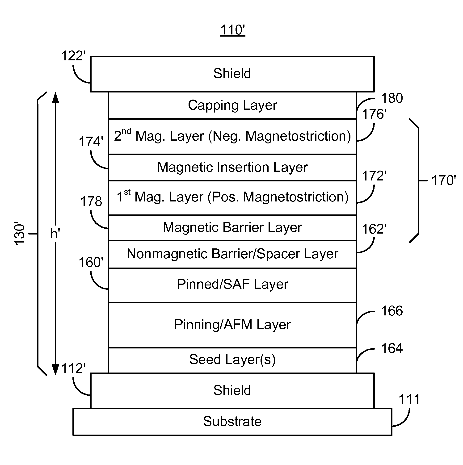
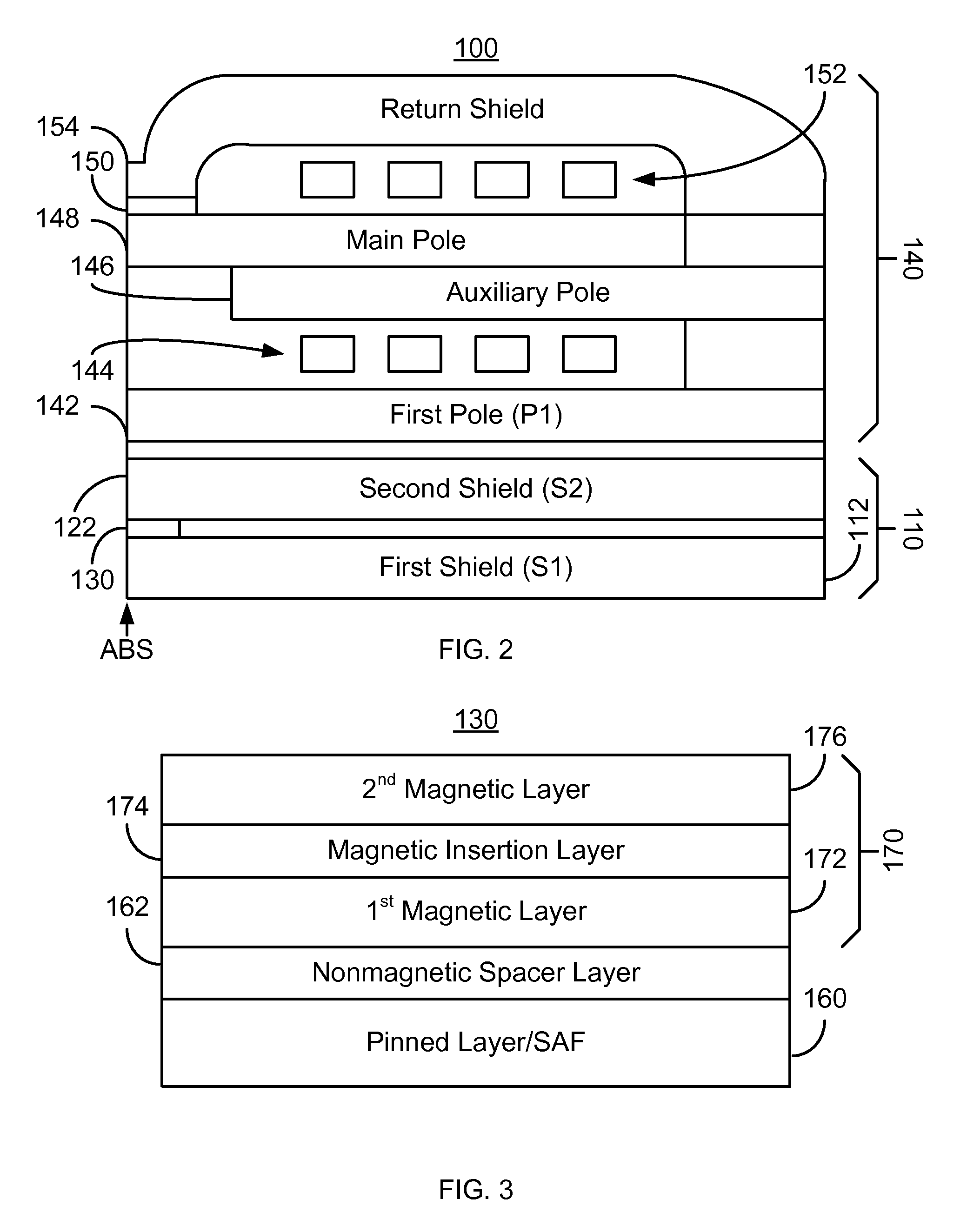
[0014]FIG. 2 depicts a magnetic head 100. The magnetic head includes a magnetic read transducer 110 and write transducer 140. FIG. 3 depicts an exemplary embodiment of a magnetic structure 130 that may be used as the read sensor of the magnetic head 100. However, in other embodiments, the magnetic structure 130 may be used for other purposes. Further, the magnetic structure 130 is shown in a current-perpendicular-to-plane (CPP) configuration, and thus is attached to the shields 112 and 122. However, in another embodiment, a gap may exist between the magnetic structure 130 and the shields 112 and / or 122. Referring to FIGS. 2-3, in another embodiment, the head 100 might include only the read transducer 110. The head 100 may reside on a slider (not shown) of a disk drive (not shown). The head 100 is also described in the context of particular layers. However, in some embodiments, such layers may include sub-layer(s). For clarity, FIGS. 2-3 are not drawn to scale.

[0015]The write transdu...


PUM

PropertyMeasurementUnit
thicknessaaaaaaaaaa
thicknessaaaaaaaaaa
thicknessaaaaaaaaaa

Abstract

A method and system for providing a magnetic structure in magnetic transducer is described. The magnetic structure includes a pinned layer, a nonmagnetic spacer layer, and a free layer. The nonmagnetic spacer layer is between the pinned layer and the free layer. The free layer includes a first magnetic layer, a second magnetic layer, and a magnetic insertion layer between the first magnetic layer and the second magnetic layer. The first magnetic layer has a first magnetostriction. The second magnetic layer has a second magnetostriction opposite to the first magnetostriction. The magnetic insertion layer provides a growth texture barrier between the first magnetic layer and the second magnetic layer.

Description

BACKGROUND[0001]FIG. 1 depicts a portion of a conventional magnetic transducer 10, such as a conventional read transducer or other device. The conventional transducer 10 resides on a conventional substrate 11, such as an AlTec substrate. The conventional transducer 10 includes a conventional bottom shield 12, conventional shield 12, conventional antiferromagnetic (AFM) layer 18, conventional sensor 20, and conventional top shield 40. The transducer 10 also typically includes seed layer(s) (not shown) between the conventional AFM layer 14 and the conventional shield 12. The conventional shields 12 and 30 typically include NiFe and are formed by plating.[0002]The conventional sensor 20 typically includes an antiferromagnetic layer 14, a pinned layer that is usually a synthetic antiferromagnetic (SAF) layer 22, a nonmagnetic layer 24, a free layer 30, and a capping layer 26. The conventional SAF layer 22 typically includes two ferromagnetic layers (not separately shown) separated by a ...

Claims


Application Information

Patent Timeline
Patent Type & Authority Patents(United States)
IPC IPC(8): G11B5/39
CPCG01R33/098G11B5/3906H01L43/08H01L43/10H10N50/10H10N50/85
Inventor LENG, QUNWENPARK, CHANDOGUO, YIMINKAISER, CHRISTIANPAKALA, MAHENDRAMAO, SINING
Owner WESTERN DIGITAL TECH INC
Why Eureka
Try Eureka