Apparatus and system for dampening the vibration experienced by an object

a technology of vibration and object, applied in the field of dampening the level of vibration, can solve the problems of repeat failure, loss of core flow indication, and generally longer installation time, and achieve the effect of dampening vibration and dampening vibration experienced

Active Publication Date: 2012-06-05
GE HITACHI NUCLEAR ENERGY AMERICAS
View PDF5 Cites 6 Cited by
  • Summary
  • Abstract
  • Description
  • Claims
  • Application Information

AI Technical Summary

Benefits of technology

[0010]In accordance with an embodiment of the present invention, an apparatus for dampening vibration experienced by an object integrated with a structure within a reactor pressure vessel (RPV) of a nuclear power plant; wherein the apparatus comprises: a bearing plate configured for providing a barrier between an object and a structure, wherein the structure is located within a reactor pressure vessel (RPV) of a nuclear power plant; a lower section for holding a portion of the object, wherein a first surface of the lower section integrates with the bearing plate and a second surface of the lower section holds a portion of the object; an upper section for holding another portion of the object, wherein the upper section integrates with the bearing plate and mates with the lower section; wherein the lower section and the upper section cooperatively secure the object at a distance from a facing surface of the bearing plate, and allows for dampening of a vibration experienced by the object.
[0011]In accordance with another embodiment of the present invention, a system for reducing the vibration experienced by a pipe within a nuclear reactor pressure vessel (RPV), the system comprising: a nuclear fuel core comprising a plurality of fuel bundle assemblies; a inlet; a sparger pipe; a core spray line; and a clamp comprising an upper section and a lower section; wherein the clamp is connected to a portion of the sparger pipe to reduce a level of vibration experience by the sparger pipe; and wherein the clamp applies a compressive load to the sparger pipe and positions the sparger pipe and a distance from the core spray line.

Problems solved by technology

This can result in loss of the indication of core flow, which may require shutdown of the RPV 10.
There are a few possible problems with the currently known systems for dampening the vibration.
Currently known systems involve re-welding the lugs 110, which may lead to a repeat failure.
These systems generally require longer installation time and expose operators to longer period of radioactivity.

Method used


Image

  • Apparatus and system for dampening the vibration experienced by an object
  • Apparatus and system for dampening the vibration experienced by an object
  • Apparatus and system for dampening the vibration experienced by an object

Examples


Embodiment Construction

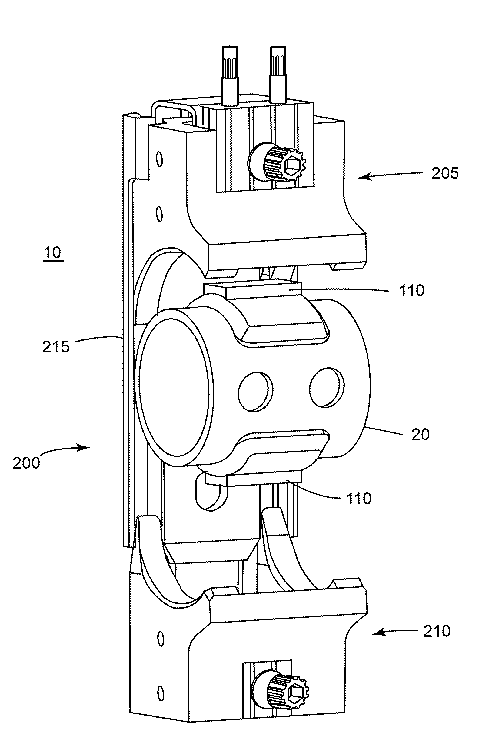
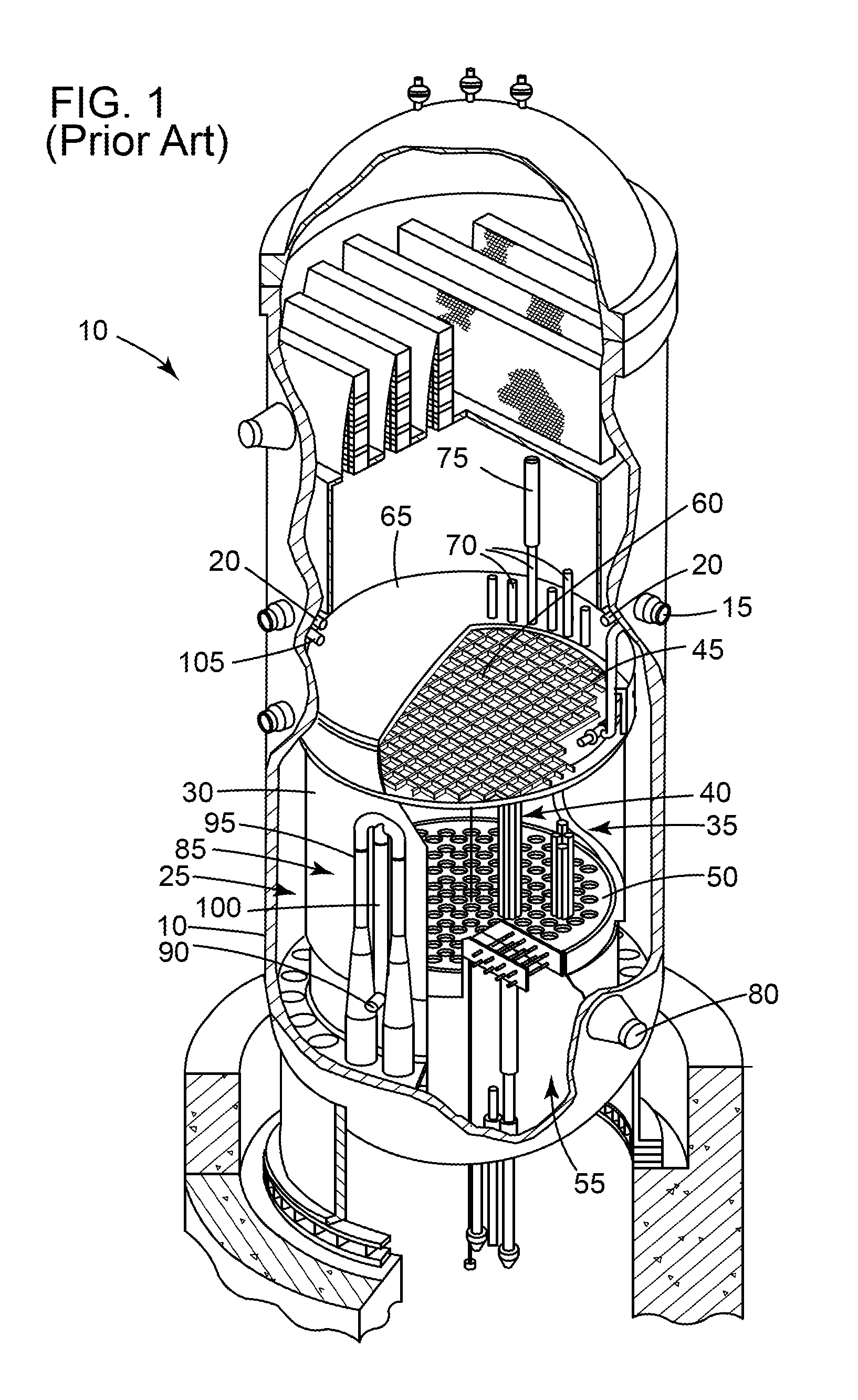
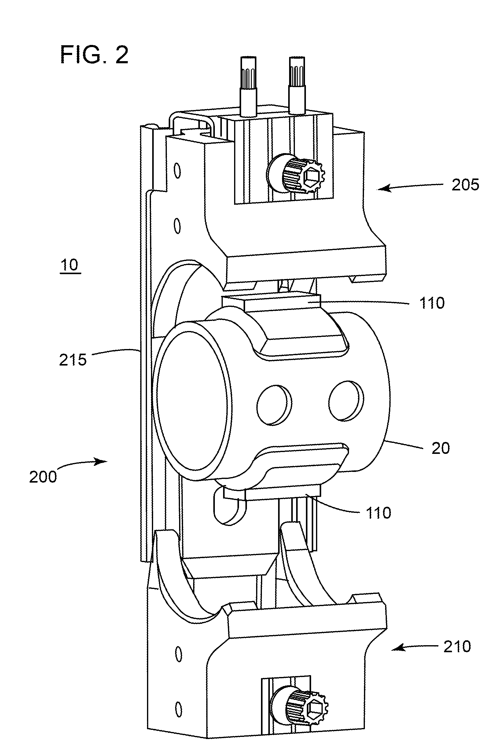
[0017]Certain terminology is used herein for convenience only and is not to be taken as a limitation on the invention. For example, words such as “upper,”“lower,”“left,”“front”, “right,”“horizontal,”“vertical,”“upstream,”“downstream,”“fore”, and “aft” merely describe the configuration shown in the Figures. Indeed, the components may be oriented in any direction and the terminology, therefore, should be understood as encompassing such variations unless specified otherwise. Furthermore, the following discussion focuses on an embodiment of the present invention integrated with the sparger system of the RPV 10. Other embodiments of the present invention may be integrated with other systems that require a dampening of and / or frequency change in vibration.

[0018]The present invention has the technical effect of reducing the level of vibration experienced by a line, such as, but not limiting of, a pipe, a cable, tubing, or the like, that is connected to at least one separate structure. For ...


PUM


Abstract

An embodiment of the present invention may reduce the level of vibration experienced by a line, such as, but not limiting of, a pipe, a cable, tubing, or the like, that is connected to at least one separate structure. For example, but not limiting of, the structure includes: a reactor pressure vessel, a sparger pipe, steam generator, a pipe, a pressure vessel, a heat exchanger, a pump, a condenser, a tank, or the like. An embodiment of the present invention may provide support and a preload to the line at a new location or may replace an existing support, such as, but not limiting of, a weld; which may alter the natural frequencies to avoid resonance from occurring when the structure(s) is excited.

Description

BACKGROUND OF THE INVENTION[0001]The present application relates generally to nuclear reactors; and more particularly to, a system for dampening the level of vibration experienced by system piping within a nuclear reactor pressure vessel.[0002]One type of nuclear reactor, a conventional boiling water reactor (BWR) is shown in FIG. 1. During operation of the reactor, coolant water circulating inside a reactor pressure vessel (RPV) 10 is heated by nuclear fission produced in the nuclear fuel core 35. Feedwater is admitted into the RPV 10 via a inlet 15 and a sparger pipe 20, which is adjacent a core spray line 105. The flows downwardly through a downcomer annulus 25, which is an annular region between RPV 10 and a core shroud 30.[0003]The core shroud 30 is a stainless steel cylinder that surrounds the nuclear fuel core 35, which includes a plurality of fuel bundle assemblies 40 (only a few are illustrated in FIG. 1). A top guide 45 and a core plate 50 supports each of the fuel bundle...

Claims


Application Information

Patent Timeline
Patent Type & Authority Patents(United States)
IPC IPC(8): G21C9/00
CPCF16L3/10F16L55/035G21C13/032Y02E30/40G21C15/00Y02E30/30
Inventor WROBLEWSKI, NORBERT B.DEFILIPPIS, MICHAEL S.ANDRE, LEE J.
Owner GE HITACHI NUCLEAR ENERGY AMERICAS
Why Eureka
Try Eureka