Accommodative lens implant, controlled by the ciliary muscle

a technology of ciliary muscle and implant body, which is applied in the field of accommodating artificial lens implants, can solve the problems of state of the art, lack of crucial elements for conducting muscular forces, and low success rate of implantation, and achieve the effect of the base shape of the implant body itsel

Active Publication Date: 2012-06-12
CARL ZEISS MEDITEC AG
View PDF23 Cites 48 Cited by
  • Summary
  • Abstract
  • Description
  • Claims
  • Application Information

AI Technical Summary

Benefits of technology

[0011]In view of the preceding considerations, it is the objective of the invention to disclose a further developed accommodative lens implant controlled by the ciliary muscle and consisting of at least one or more lenses disposed on a common optical axis, which is suitable for replacing the natural lens of the eye and which provides the possibility of making an adjustment even after installation so as to produce a natural accommodation, allowing the eye to focus correctly even without corrective spectacles.
[0020]For example, by microinjection applied to the fluid depot, liquid can be removed or added with the consequence that the degree of filling, and hence the basic shape of the implant body itself, can be altered or adjusted.

Problems solved by technology

Such an implantation does not promise much success, because the lens capsule is practically impossible to close at present by surgical means.
Hence the arrangement lacks a crucial element for conducting the muscular forces into the implant.
The state of the art as described above furthermore does not make possible any basic surgical adjustments that would allow the intraocular lens implant to be installed at precisely the correct distance from the retina, so as to enable the desired optimal long- and short-distance vision.
A problematic aspect of the solution according to DE 689 02 614 T2 is the anchoring of the implant in the tender and sensitive lens capsule, which carries a corresponding risk that the capsule will be destroyed before, during or after the implantation.

Method used


Image

  • Accommodative lens implant, controlled by the ciliary muscle
  • Accommodative lens implant, controlled by the ciliary muscle
  • Accommodative lens implant, controlled by the ciliary muscle

Examples


Embodiment Construction

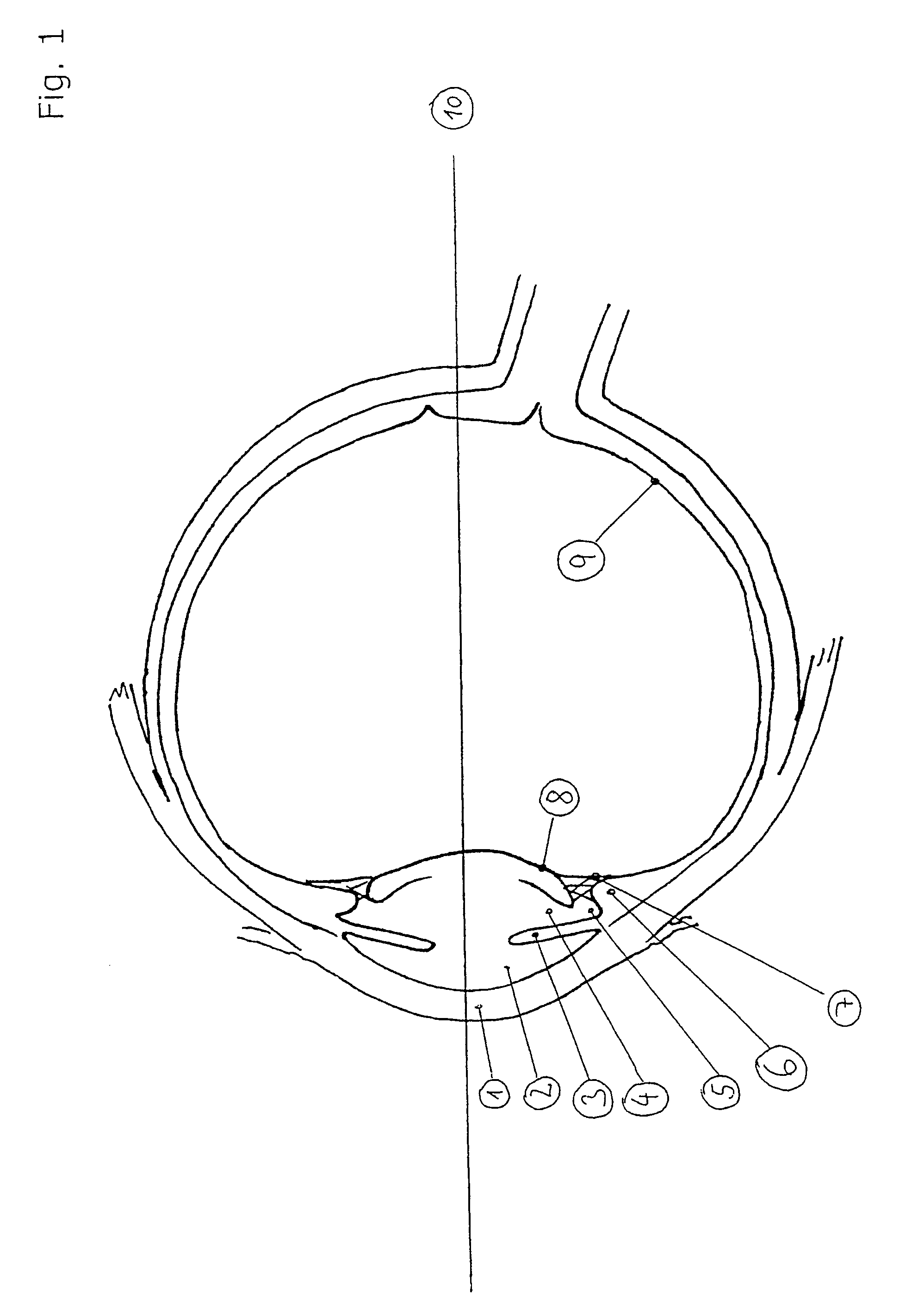
[0027]The drawing in FIG. 1 shows the cornea 1 in the anterior region of the eyeball, with anterior optic chamber 2 situated behind it. Reference numeral 3 identifies the iris of the eye.

[0028]The visual axis is labelled by the reference numeral 10. The numeral 5 identifies the sulcus between the ciliary muscles and the iris, while 6 indicates the origin of the ciliary muscles and the muscles themselves. The zonule fibers are identified by the numeral 7, the lens capsule by 8, and the retina by 9.

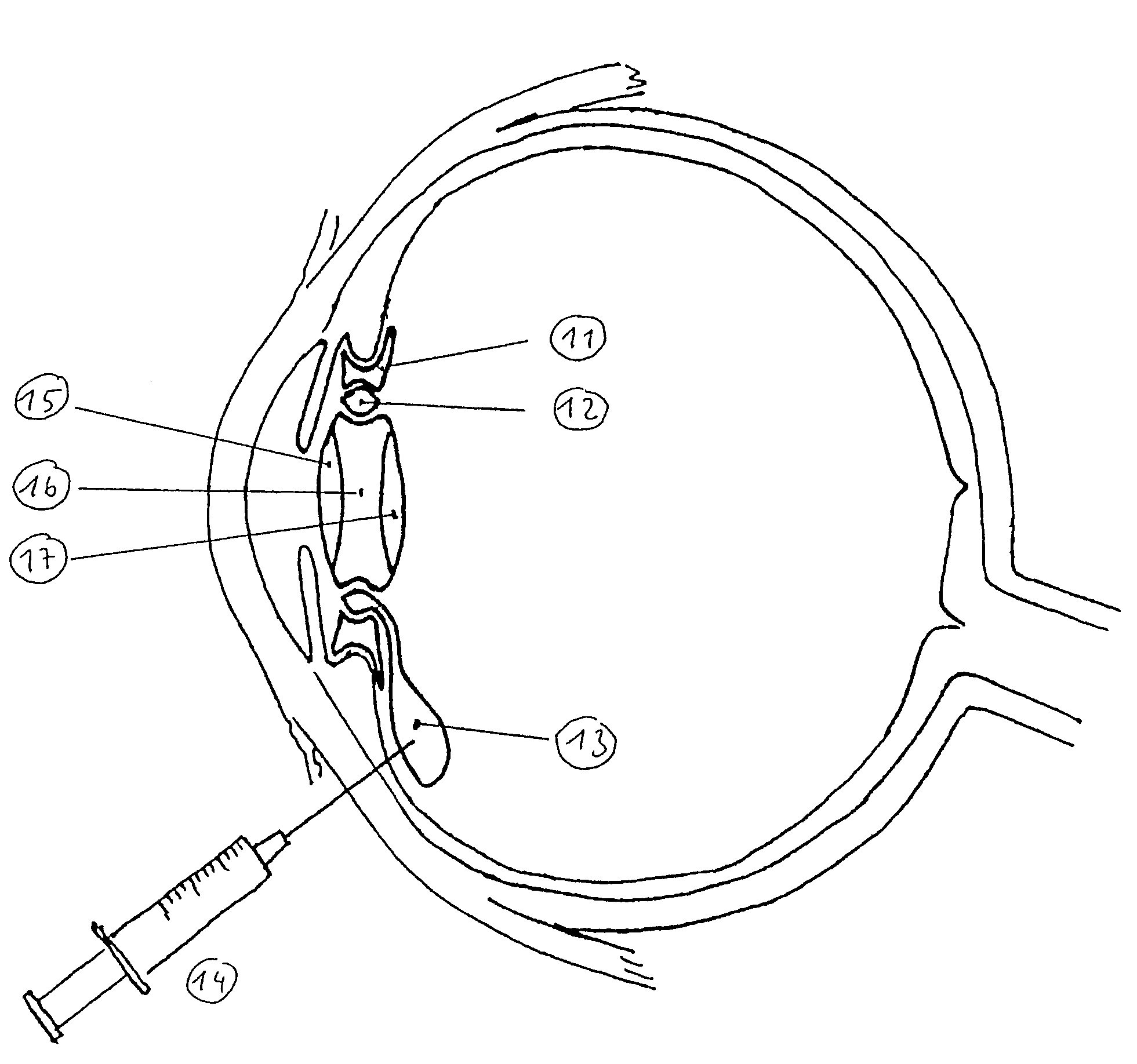
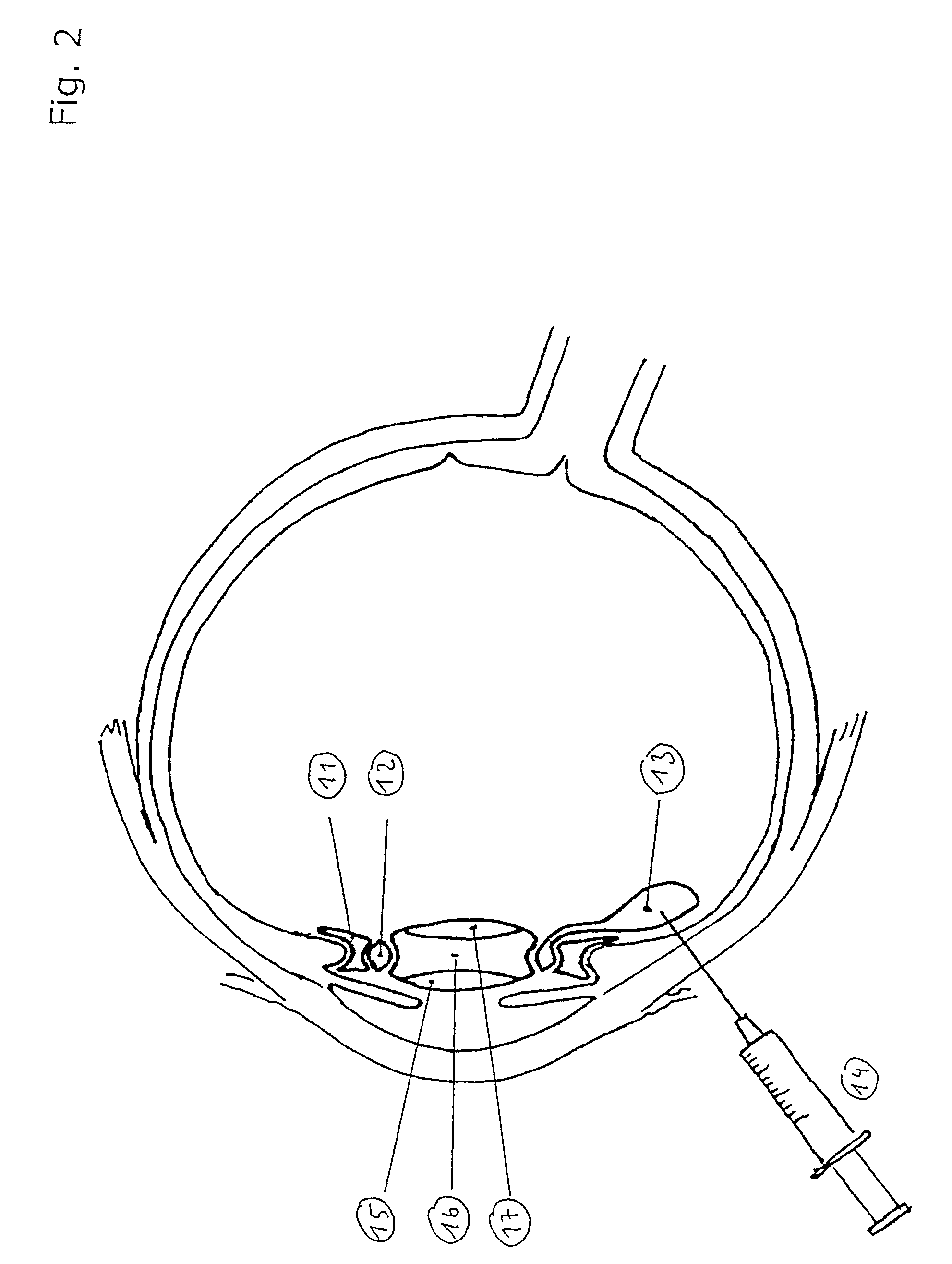
[0029]In the drawing in FIG. 2 a place holder is discernible, namely the intermobile element 11 that fixes the position of the implant, the latter consisting of outer lens 15, fluid-filled cavity 16 and inner lens 17. Between the intermobile element 11 and the implant there is another fluid depot 12 constructed as a ring, which communicates with an external injection chamber 13 so that fluid injection can be carried out by way of, for example, a syringe 14. The lens implant shown in FIG. 2 ...


PUM


Abstract

The invention relates to an accommodative lens implant controlled by the ciliary muscle, consisting of at least one or more lenses made of preferably biocompatible material and disposed on a common optical axis, the at least one lens being a component of a flexible, closed implant body that is transparent in the region of the actual lens, is engaged at its outer periphery with the ciliary muscle, and has a main axis that coincides with the visual axis, and in addition at least part of the implant body with the lens or lenses comprises a fluid filling, such that the axial position of the lens or the lens system can be altered by activation of the ciliary muscle, the implant body being inserted in the sulcus of the posterior chamber of the eye or attached to the ciliary muscle.

Description

CROSS-REFERENCE TO RELATED APPLICATIONS[0001]This application is a divisional of and is based upon and claims the benefit of priority under 35 U.S.C. §120 for U.S. Ser. No. 10 / 569,444, filed Jan. 31, 2007, which is a national stage of PCT / EP04 / 09501, filed Aug. 25, 2004, and claims the benefit of priority under 35 U.S.C. §119 from German Application Nos. 103 39 266.1, filed Aug. 26, 2003, and 103 46 024.1, filed Oct. 2, 2003, the entire contents of each which are incorporated herein by reference.DESCRIPTION[0002]The invention relates to a lens implant that is capable of accommodation under the control of the ciliary muscle and consists of at least one or several lenses made of a preferably biocompatible material, which are disposed on a common optical axis.BACKGROUND[0003]The publication EP 0 793 460 B1 discloses an accommodative artificial lens implant employing optics that move in reaction to changes in the ciliary muscle. The intraocular lens arrangement used there is intended to...

Claims


Application Information

Patent Timeline
Patent Type & Authority Patents(United States)
IPC IPC(8): A61F2/16
CPCA61F2/1613A61F2/1629A61F2/1648A61F2/1635A61F9/00781
Inventor SCHEDLER, MARKUS
Owner CARL ZEISS MEDITEC AG
Why Eureka
Try Eureka