Separator for fuel cell
a fuel cell and separator technology, applied in the field of fuel cells, can solve the problems of difficult to form an optional flow channel structure, uneven flow of reacting gas, and easy cracks
- Summary
- Abstract
- Description
- Claims
- Application Information
AI Technical Summary
Benefits of technology
Problems solved by technology
Method used
Image
Examples
embodiment 1
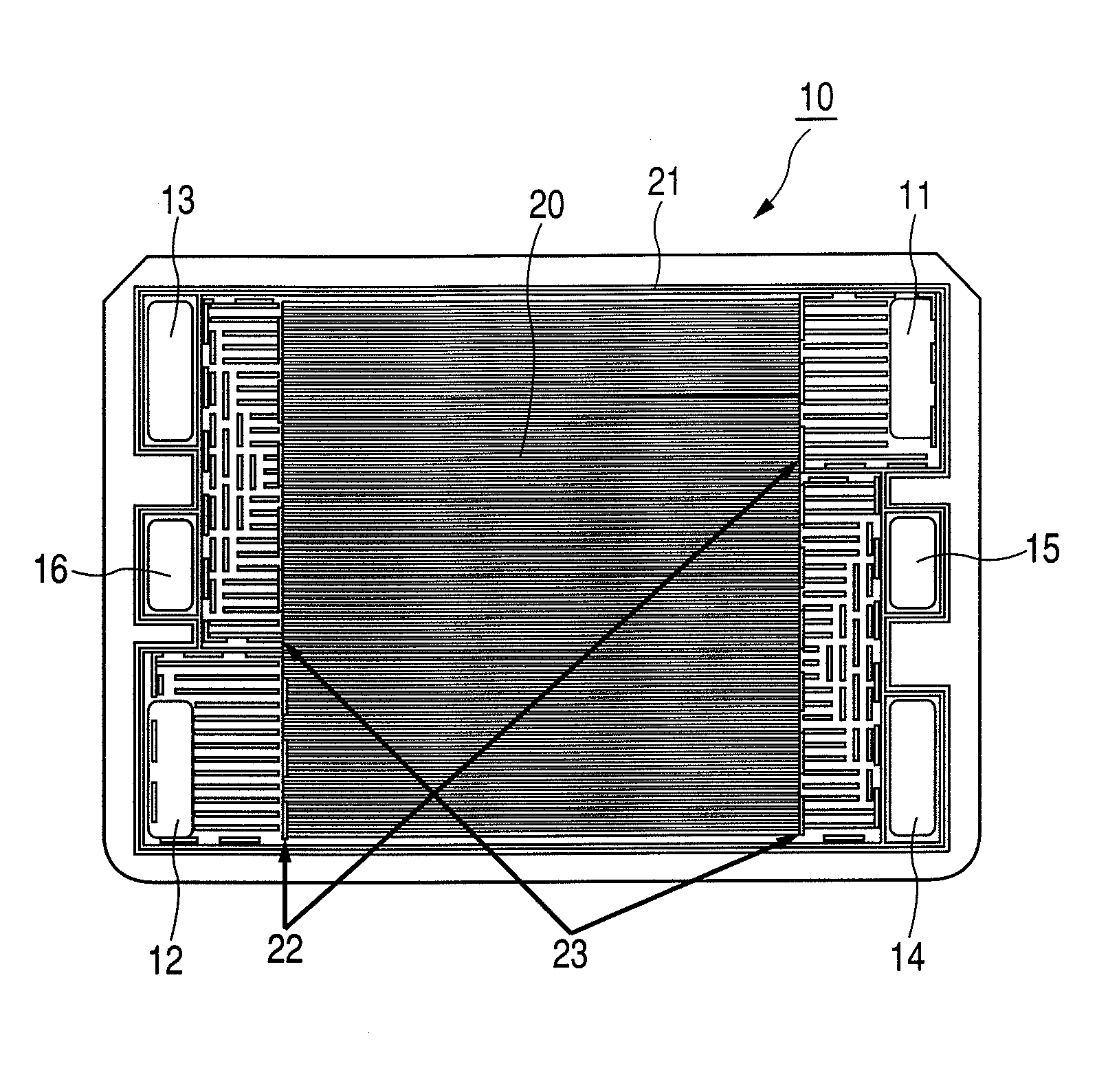
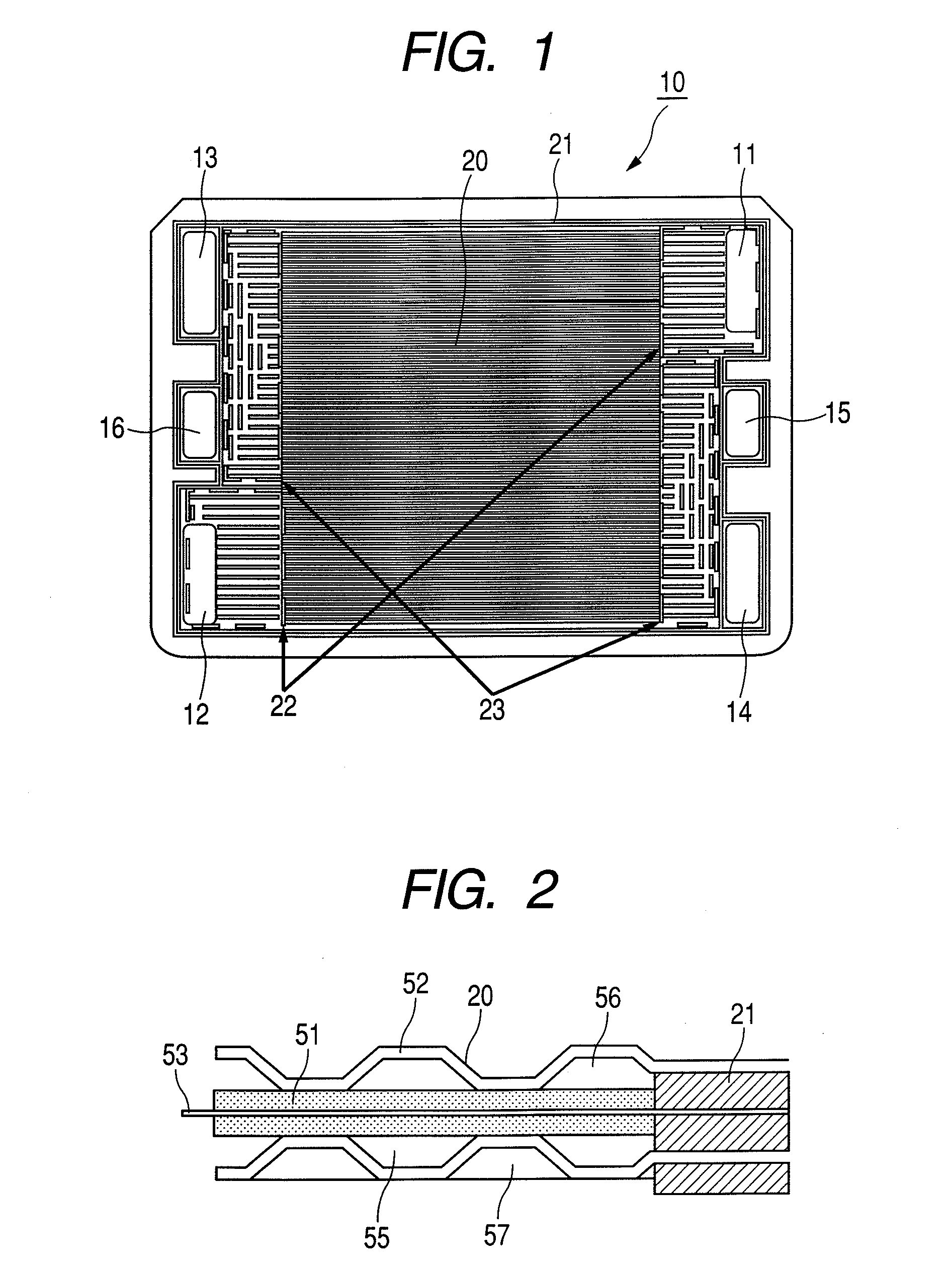
[0029]FIG. 1 is a schematic view to show an embodiment of a separator 10 for a polymer electrolytic fuel cell of the present invention. With the separator 10, reacting gas sealing units 21, reacting gas manifold junction units 22, and reacting gas rectification units 23 are formed of an elastic body, respectively, over a pressed metal sheet obtained by press working on a metal sheet so as to form a reacting gas flow channel unit 20 where a reacting gas is supplied to a power generation face.
[0030]As shown in the FIG. 1, a fuel gas supply manifold 11 for supplying a fuel gas to a surface of the separator 10, and a fuel gas discharge manifold 12 for discharging the fuel gas out of the separator 10 are formed over the separator 10. Further, there are formed an oxidizing gas supply manifold 13 for supplying an oxidizing agent gas (for example, air, and so on) to the separator 10, an oxidizing gas discharge manifold 14 for discharging the oxidizing agent gas out of the separator 10, a co...
embodiment 2
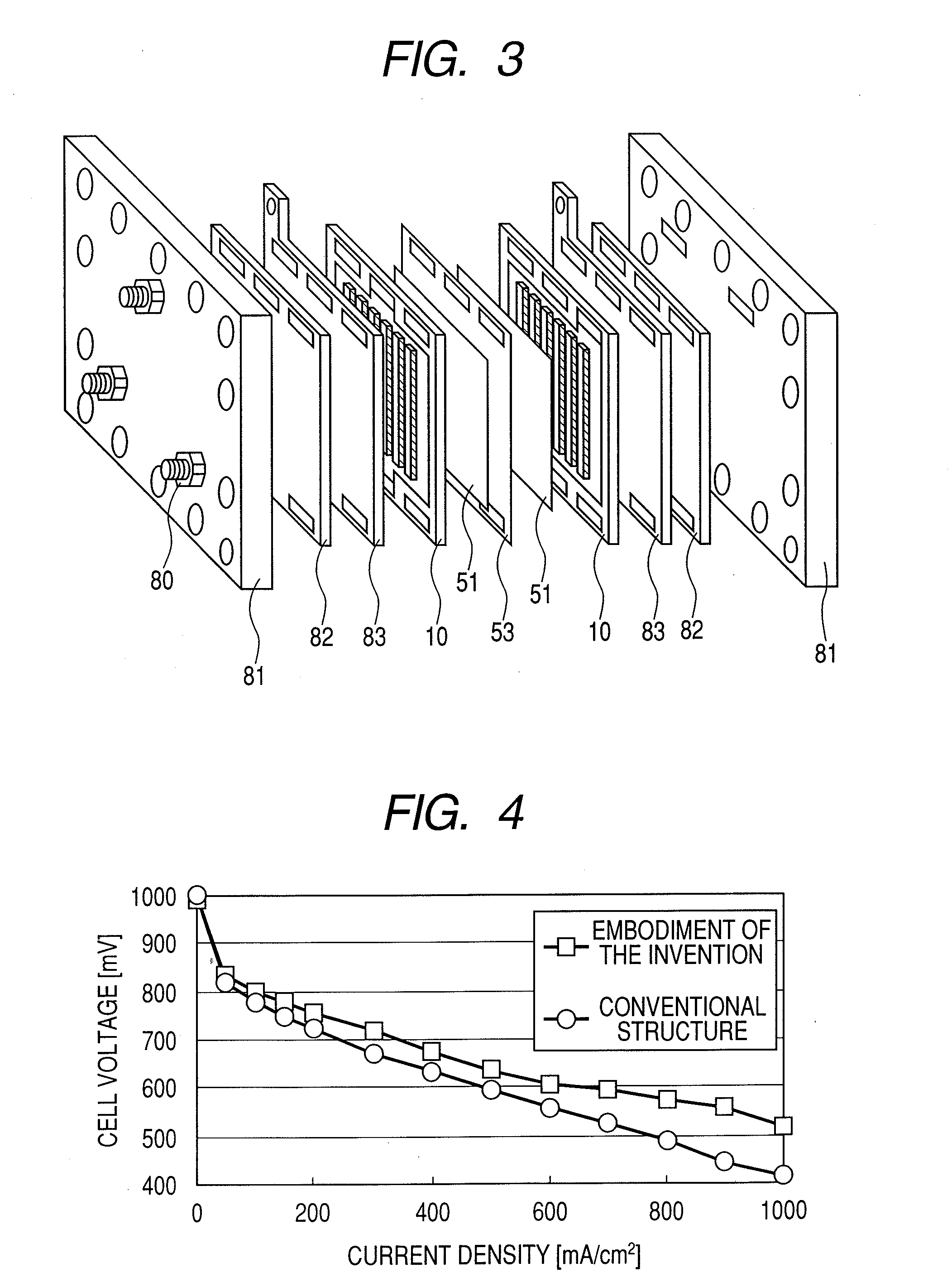
[0049]In an electrolytic fuel cell stack including the separator in the another embodiment of the present invention, in order to conduct a power generation test using the separator described, GORE SELECT III PRIMEA 5561 (manufactured by Japan Goretex Co., Ltd.) was used for an MEA 53, and CARBEL CL (manufactured by Japan Goretex Co., Ltd.) was used for a gas diffusion layer 51. A separator substrate 72 of the separator 10 is made of stainless steel, and is structured such that projections and depressions formed by press working are provided on both sides of the central part thereof. Press dimensions are 116×117 mm, and electrodes of the MEA 53 are fabricated so as to match the press dimensions.
[0050]FIG. 3 is an exploded view of a fuel cell including the separators in the another embodiment of the present invention, showing constituent members, and a layout thereof. The MEA 53 is disposed at the center of the fuel cell, and is sandwiched between gas diffusion layers 51 in such a way...
PUM
| Property | Measurement | Unit |
|---|---|---|
| thickness | aaaaa | aaaaa |
| thickness | aaaaa | aaaaa |
| contact pressure | aaaaa | aaaaa |
Abstract
Description
Claims
Application Information
 - R&D
- Intellectual Property
- Life Sciences
- Materials
- Tech Scout
- Unparalleled Data Quality
- Higher Quality Content
- 60% Fewer Hallucinations
Browse by: Latest US Patents, China's latest patents, Technical Efficacy Thesaurus, Application Domain, Technology Topic, Popular Technical Reports.
© 2025 PatSnap. All rights reserved.Legal|Privacy policy|Modern Slavery Act Transparency Statement|Sitemap|About US| Contact US: help@patsnap.com


