Seat belt warning system

Active Publication Date: 2012-06-12
APTIV TECH LTD
View PDF18 Cites 4 Cited by
  • Summary
  • Abstract
  • Description
  • Claims
  • Application Information

AI Technical Summary

Benefits of technology

[0004]It is the object of the invention to provide an improved safety belt warning system of the kind mentioned hereinbefore, in which the above problems are eliminated. In this case with a simple construction in particular easy evaluation of the sensor signals is to be made possible, and a reliable manner of operation substantially independent of ambient influences is to be ensured.
[0006]The sensor mat of such a safety belt warning system can in particular be arranged underneath the foam of a respective vehicle seat, so that the safety belt warning system has no effect on comfort while sitting. Accordingly, there are no restrictions with respect to surface design of the seat either. As the capacitances of two capacitors subject to the same environmental conditions can be used for evaluation of the variations caused by a respective load, the system is stable in relation to environmental influences. Also, with use of the capacitances of the two capacitors for evaluation, the respective evaluating device can be kept relatively simple.
[0019]With the safety belt warning system according to the invention, therefore, a sensor which was previously arranged directly under the seat cover (“a surface sensor”) can be replaced by a capacitive sensor mat which is arranged under the foam of the respective seat and of which the capacitance values are evaluated by means of a balanced bridge circuit. The sensor mat as such can for example comprise a doubly folded flexible film or base mat with a silicone rubber inlay as the flexible dielectric upper layer, and a non-elastic dielectric layer having a three-dimensional knitted spacer fabric as the lower layer. With such a construction two capacitor elements are formed which have at least substantially the same capacitance when the seat is empty, that is, not loaded. If on the other hand the seat concerned is loaded, the upper capacitor varies its capacitance considerably, this being due to the correspondingly high compression of the silicone rubber inlay. On the other hand, the lower layer remains at least substantially unchanged, so that correspondingly the capacitance of the lower capacitor remains at least substantially unchanged. For evaluation of the sensor signals and for generation of the belt warning signal, a simple bridge circuit is sufficient, for example. By a suitable design, effects caused by the ambient conditions such as in particular humidity can be compensated, as the two capacitors vary in the same way due to moisture and ageing effects.
[0020]The safety belt warning system according to the invention consequently affords in particular the following advantages.
[0021]The comfort while sitting is not impaired, as the safety belt warning system or the sensor mat can be arranged underneath the foam of the seat concerned. Also, the system does not in any way affect the surface design. Furthermore, optimum stability in relation to ambient conditions is achieved. For evaluation, ordinary electronic circuits are sufficient, thus reducing the costs accordingly.
[0022]Seat occupation is therefore possible in an extremely cheap and reliable manner. Such seat occupation can be detected for example when the weight concerned is greater than 30 kg. An empty seat can for example be detected when the weight concerned is less than 6 kg.

Problems solved by technology

Because such a sensor is arranged under the seat cover, a number of problems arise.
The design of the seat cover can have an effect on the performance of the sensor and so is subject to corresponding restrictions.

Method used


Image

  • Seat belt warning system
  • Seat belt warning system
  • Seat belt warning system

Examples


Embodiment Construction

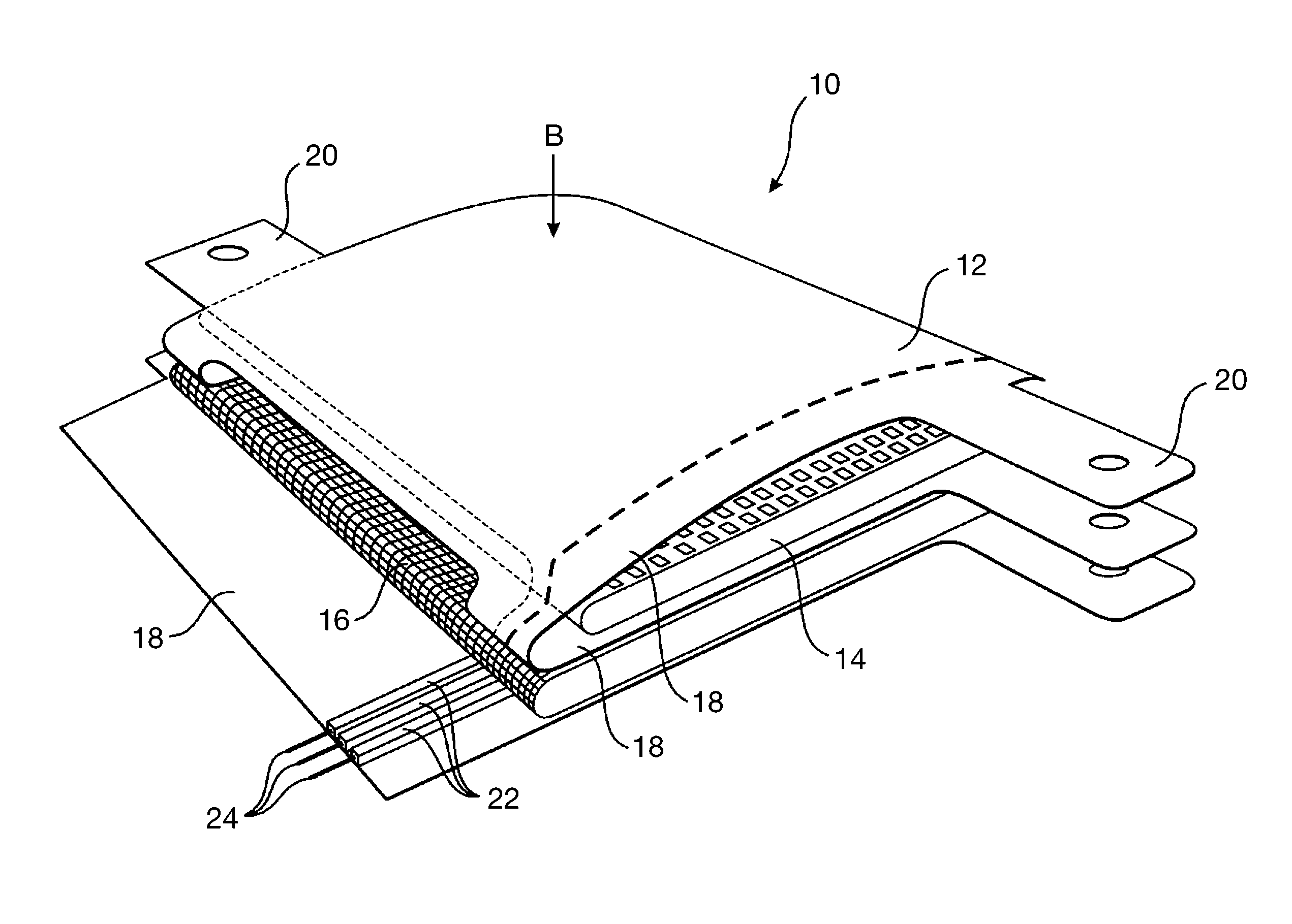
[0033]FIG. 1 shows in a schematic perspective view an embodiment of a sensor mat 10 by way of example used for the detection of a force acting on its surface, of a safety belt warning system designed in particular for vehicles.

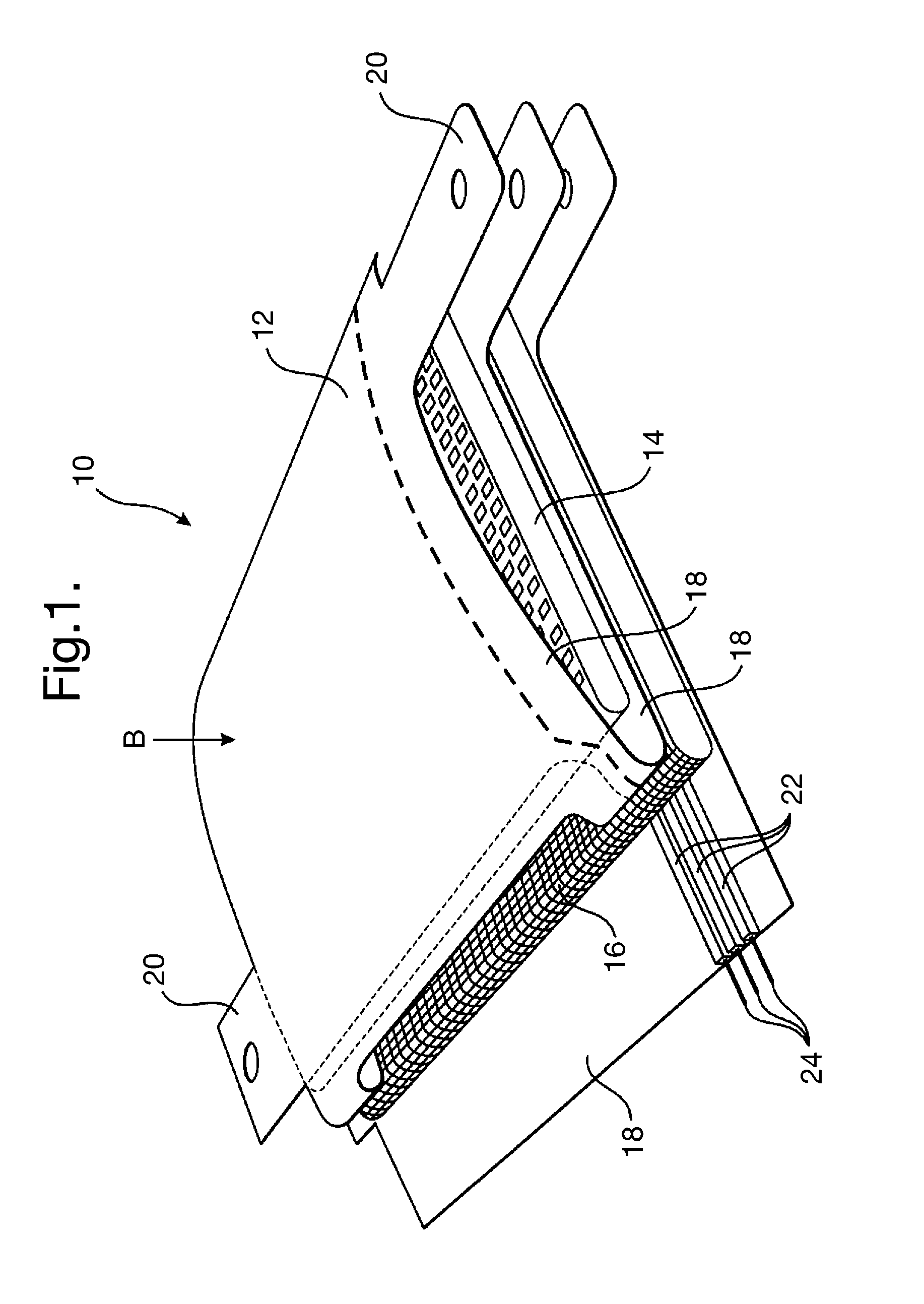
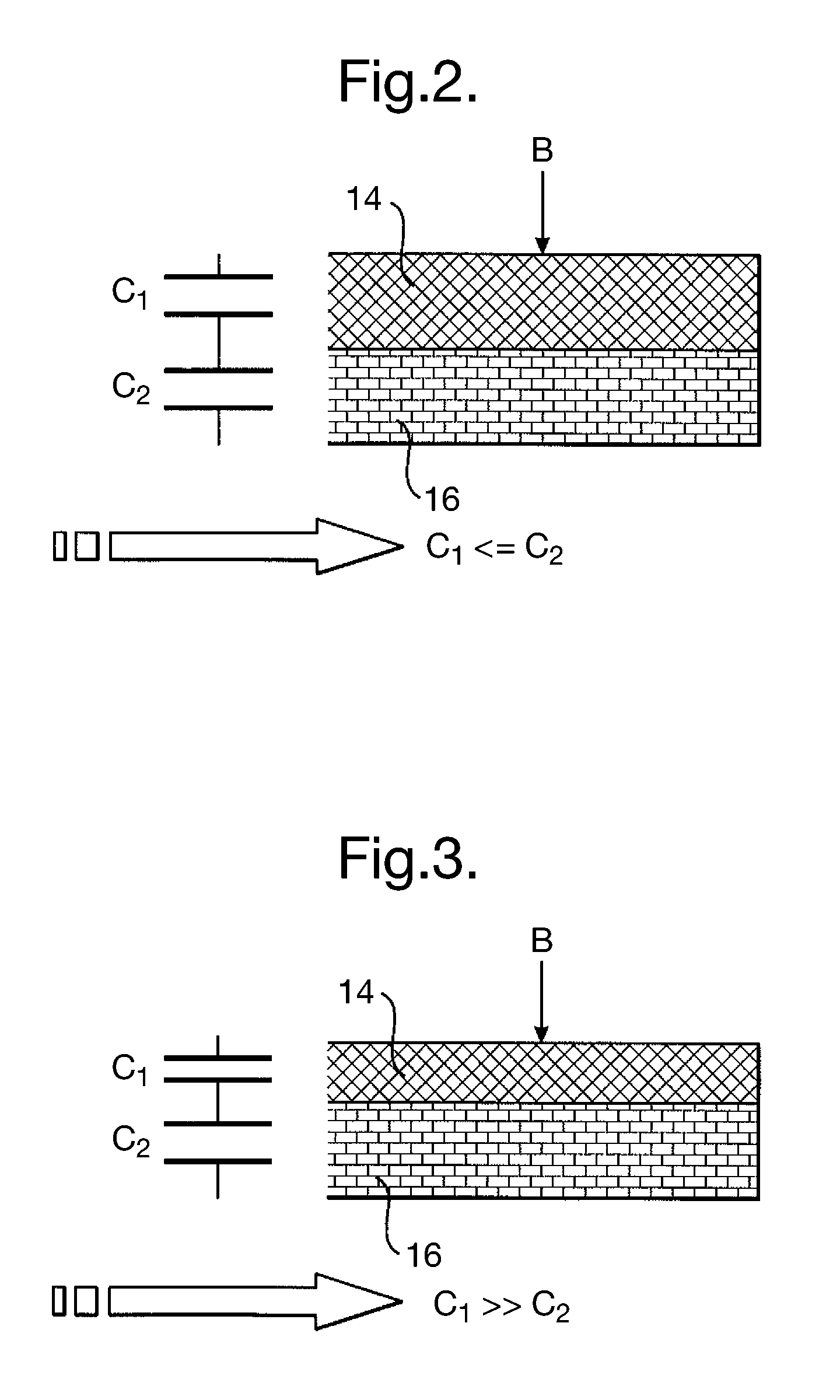
[0034]As can be seen with the aid of FIG. 1, the sensor mat 10 comprises, for the formation of two electrical capacitors C1, C2 (cf. for example FIGS. 2, 3 and 6), two dielectric layers 14, 16 located one above the other in sandwich fashion and arranged in each case between electrically conductive coats 12 (cf. FIG. 4). In this case the two dielectric layers 14, 16 have different compressibility at least in the direction of loading caused by the force, so that the capacitances of the two capacitors C1, C2 vary differently with a respective load on the sensor mat 10. The direction of loading is marked with a respective arrow “B” in FIGS. 1 to 3.

[0035]The more compressible dielectric layer 14 can be arranged for example above the less compressible or incompressi...


PUM


Abstract

A safety belt warning system for vehicles comprises a sensor mat for the detection of a force acting on its surface, which includes, for the formation of two electrical capacitors, two dielectric layers which are located one above the other in sandwich fashion and arranged in each case between electrically conductive coats, and which have different compressibility at least in the direction of loading due to force, so that the capacitances of the two capacitors vary differently with a load on the sensor mat.

Description

TECHNICAL FIELD[0001]The invention concerns a safety belt warning system for vehicles, having a sensor mat for the detection of a force acting on its surface.BACKGROUND OF THE INVENTION[0002]Vehicles are increasingly being fitted with safety belt warning systems which, for a respective vehicle seat loaded by the weight of a person, generate a warning signal in the event that the safety belt is not done up. A conventional safety belt warning system includes for example a graphite composite-based sensor on a PET (e.g. polyethylene terephthalate) film with a contact dye of which the resistance varies as a function of the pressure applied. Because such a sensor is arranged under the seat cover, a number of problems arise. Thus the sensor affects the comfort when sitting. The design of the seat cover can have an effect on the performance of the sensor and so is subject to corresponding restrictions.[0003]Also, the foam is subject to certain restrictions with respect to the surface design...

Claims


Application Information

Patent Timeline
Patent Type & Authority Patents(United States)
IPC IPC(8): G08B21/00B60Q1/00
CPCB60N2/002B60R22/48B60R21/01516G01L1/144G01G19/4142B60R2022/4858
Inventor FISCHERFISCHER, CHRISTIAN A.FRUEND, MARCELNIEDERHAGEN, KAI
Owner APTIV TECH LTD
Why Eureka
Try Eureka