[0004]It is the object of the invention to provide an improved safety belt warning
system of the kind mentioned hereinbefore, in which the above problems are eliminated. In this case with a simple construction in particular easy evaluation of the sensor signals is to be made possible, and a reliable manner of operation substantially independent of ambient influences is to be ensured.
[0006]The sensor mat of such a safety belt warning
system can in particular be arranged underneath the foam of a respective vehicle seat, so that the safety belt warning
system has no effect on comfort while sitting. Accordingly, there are no restrictions with respect to surface design of the seat either. As the capacitances of two capacitors subject to the same environmental conditions can be used for evaluation of the variations caused by a respective load, the system is stable in relation to environmental influences. Also, with use of the capacitances of the two capacitors for evaluation, the respective evaluating device can be kept relatively simple.
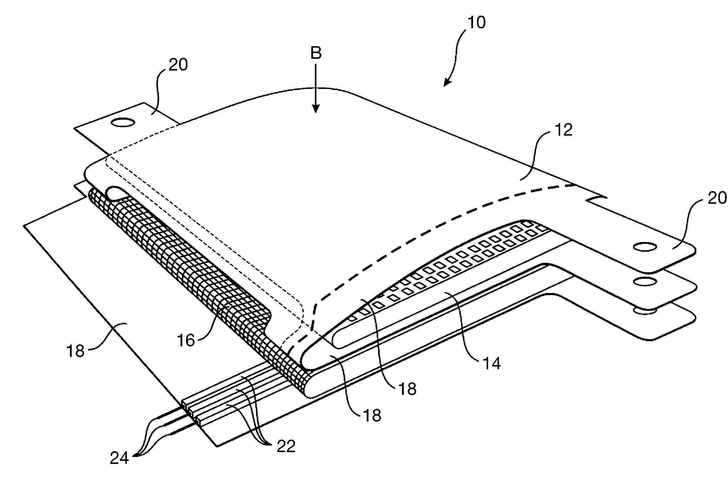
[0019]With the safety belt warning system according to the invention, therefore, a sensor which was previously arranged directly under the seat cover (“a surface sensor”) can be replaced by a capacitive sensor mat which is arranged under the foam of the respective seat and of which the
capacitance values are evaluated by means of a balanced
bridge circuit. The sensor mat as such can for example comprise a doubly folded flexible film or base mat with a
silicone rubber inlay as the flexible
dielectric upper layer, and a non-elastic
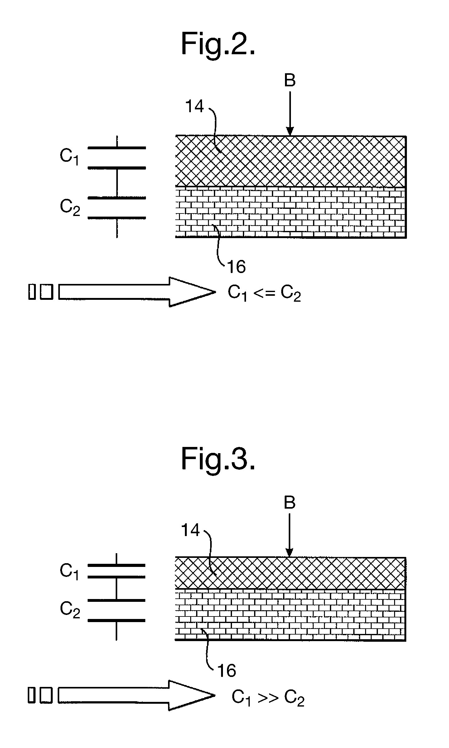
dielectric layer having a three-dimensional knitted spacer fabric as the lower layer. With such a construction two
capacitor elements are formed which have at least substantially the same
capacitance when the seat is empty, that is, not loaded. If on the other hand the seat concerned is loaded, the upper
capacitor varies its
capacitance considerably, this being due to the correspondingly high compression of the
silicone rubber inlay. On the other hand, the lower layer remains at least substantially unchanged, so that correspondingly the capacitance of the lower
capacitor remains at least substantially unchanged. For evaluation of the sensor signals and for generation of the belt warning
signal, a simple
bridge circuit is sufficient, for example. By a suitable design, effects caused by the ambient conditions such as in particular
humidity can be compensated, as the two capacitors vary in the same way due to
moisture and
ageing effects.
[0020]The safety belt warning system according to the invention consequently affords in particular the following advantages.
[0021]The comfort while sitting is not impaired, as the safety belt warning system or the sensor mat can be arranged underneath the foam of the seat concerned. Also, the system does not in any way affect the surface design. Furthermore, optimum stability in relation to ambient conditions is achieved. For evaluation, ordinary electronic circuits are sufficient, thus reducing the costs accordingly.
[0022]Seat occupation is therefore possible in an extremely cheap and reliable manner. Such seat occupation can be detected for example when the weight concerned is greater than 30 kg. An empty seat can for example be detected when the weight concerned is less than 6 kg.

