Pipe coupler and gasket with positive retention and sealing capability

a technology of positive retention and sealing capability, which is applied in the direction of hose connections, couplings, mechanical devices, etc., can solve the problems of clogging of pipes, improper seated of coupler gaskets, and damage to gaskets or other leakage, so as to reduce the locations of people's positions

Active Publication Date: 2012-06-19
BRAY INT INC
View PDF12 Cites 46 Cited by
  • Summary
  • Abstract
  • Description
  • Claims
  • Application Information

AI Technical Summary

Benefits of technology

[0016]The gasket retaining elements on the semi-circular elements preferably comprise projections or raised tabs or features disposed in a circumferentially extending spaced apart array about the radial outer periphery of the cavities or channels, and the elements on the gasket comprise correspondingly located receptacles sized and shaped for receiving and engaging the retaining elements when the gasket is shaped to the circumference of the cavity or channel. In this regard, the gasket will typically comprise a flexible elastomer or rubber material with at least some resiliency, having a generally straight overall free state shape, at least initially, but can also comprise a pre-curved shape. In either instance, the gasket will typically be required to be curved or bent, at least at first, typically manually, to a curvature having a radius marginally smaller than the radius of the cavity or channel of the semi-circular element in which it is to be received and used. As a result, the circumferential surfaces defining and bounding the receptacles along the radial outer periphery will be deformed, e.g., spread apart or expanded at least marginally, so as to more easily receive the respective retaining elements. Then, when the gasket is released so as to seat in the cavity or channel, it will resiliently conform to the curved shape thereof, and compress about and grip the respective retaining elements, for retention in the cavity or channel. This retention also advantageously holds the gasket segments evenly at least about an extended intermediate region of the circumference thereof, to prevent the gasket from sliding or moving along the inner circumferences of the semi-circular elements as the semi-circular elements are closed or brought together about the ends of two pipes or a pipe and a fitting for coupling, to avoid bunching of the gasket which can interfere with or prevent closure of the coupler, and unevenly compress or load the gasket in the circumferential direction.
[0018]As a preferred feature of the clamping mechanism, it is configured to hold the second end portions of the semi-circular elements together when spread apart when the coupler is open. As a result, the coupler in the open configuration can be placed on a pipe end (without requiring sliding the gasket thereover as with an annular gasket), and held in place with just one hand without risk of the clamping mechanism coming apart, to allow the other hand to be used for handling the other pipe for positioning it for coupling. When the pipes are positioned for coupling, the clamping mechanism of the coupler can then be positioned about both pipe ends (again without sliding the gasket) and operated to clamp the coupler with just one hand, to couple the pipes together.
[0019]The clamping mechanism includes a handle pivotally connected with one of the semi-circular elements and to one end of a bail rod. The pivotal connection between to the handle and bail rod preferably comprises a clevis on the handle, with a pin extending through the clevis and the end of the bail rod. The portion of the end of the bail rod disposed in the clevis is configured to closely cooperate with the clevis, in particular, to have oppositely facing surfaces disposed in opposing relation to the sides of the clevis. This is advantageous, as it strengthens the joint so as to have the capability to withstand loading conditions, including tensile, compression, torsion and bending loads, anticipated to be encountered by the coupler during normal use.
[0020]As another preferred feature, each end of the bail rod is fixed or secured, at its pivotal connection to the handle or the other of the semi-circular elements, respectively, such that the bail rod can be pushed longitudinally, not just pulled as required for clamping. This is an advantageous feature, as it enables a manual force to be applied to the handle in the direction for unclamping the coupler, for also opening the coupler and releasing or breaking the coupler away from a pipe of fitting. This is advantageous, as it can eliminate need for striking the coupler with a hammer or the like to release it, and the possible damage that can result.
[0021]As still another preferred aspect of the invention, the bail rod of the clamping mechanism is configured so as to be adjustable in effective length between the points of attachment to the handle and the other semi-circular element, to enable easily and precisely adjusting operation of the clamping mechanism and the tension in the bail rod when clamped. Here, the term “effective length” denotes that portion of the length of the bail rod extending between the pivot points on the handle and on the other of the semi-circular elements.
[0023]As further preferred features of the invention, the handle has a generally C-shape when viewed from the side, including large radius edges for improved ergonomics, and such that the free end of the handle curves back toward the coupler, to provide an opening sufficiently large for receiving a gloved hand, and for reducing locations where a person's hand can be pinched against the outer side of the coupler. This shape also makes it difficult to use leverage increasing tools on the handle for closing the coupler, which can damage or break the handle or other components of the coupler.

Problems solved by technology

Or, it may be found that a pipe has become clogged, so as to require uncoupling for removal of the clog.
Or a coupler gasket may be damaged or otherwise leaking, so as to require replacement.
Problems commonly encountered when coupling pipes and fittings on bulk transports and hoppers, include that the coupler gasket can be improperly seated in the coupler as the pipes or fittings are being coupled.
The pipes can be heavy, particularly when filled or partially filled with material, and thus can be hard to handle and position for coupling by one person, which can contribute to this problem.
This can be particularly problematic with some couplers that require the bail of the coupler to be disconnected from the opposite side of the coupler to open the coupler sufficiently to place it on the pipe ends to be coupled, e.g., Sisk et al. and Heelan et al. patents and publications, or wherein the bail can remain connected, but can inadvertently disconnect, e.g., Burian et al. pate
If the gasket drags or sticks as it is pulled about the pipe ends, sealing pressure about the circumference of the coupler may be uneven.
As another problem, when uncoupling a coupler, the gasket can stick to the pipe, and / or the coupler can stick to the gasket, making removal difficult, and if force is applied, for instance, using a hammer or mallet to open the coupler, the gasket can be torn or otherwise damaged.
Further, if the clamping mechanism of many of the known couplers is improperly adjusted, more force than normally necessary may be needed to close the coupler.
This can damage the clamp, e.g., break the handle of the mechanism.
This can also damage the coupler or clamping mechanism.
Regarding adjusting the clamping mechanism, some couplers, such as those of the Sisk et al. patent and publication identified above, require adjusting nuts on opposite ends of a U-shaped bail assembly, which can be time consuming and discouraging to personnel to adjust.
Others, such as the Burian et al. and Heelan et al. couplers, use a single bail, but the adjusting nut is located so as to be very difficult to access, which also discourages adjustment.
As a result, it has been found that many of the known couplers in use in the field are improperly adjusted, so as to be susceptible to leakage and damage.
Still further, some of the known couplers have handles that are susceptible to pinching a user's hand when closed, due to close proximity of the handle to the coupler body.

Method used


Image

  • Pipe coupler and gasket with positive retention and sealing capability
  • Pipe coupler and gasket with positive retention and sealing capability
  • Pipe coupler and gasket with positive retention and sealing capability

Examples


Embodiment Construction

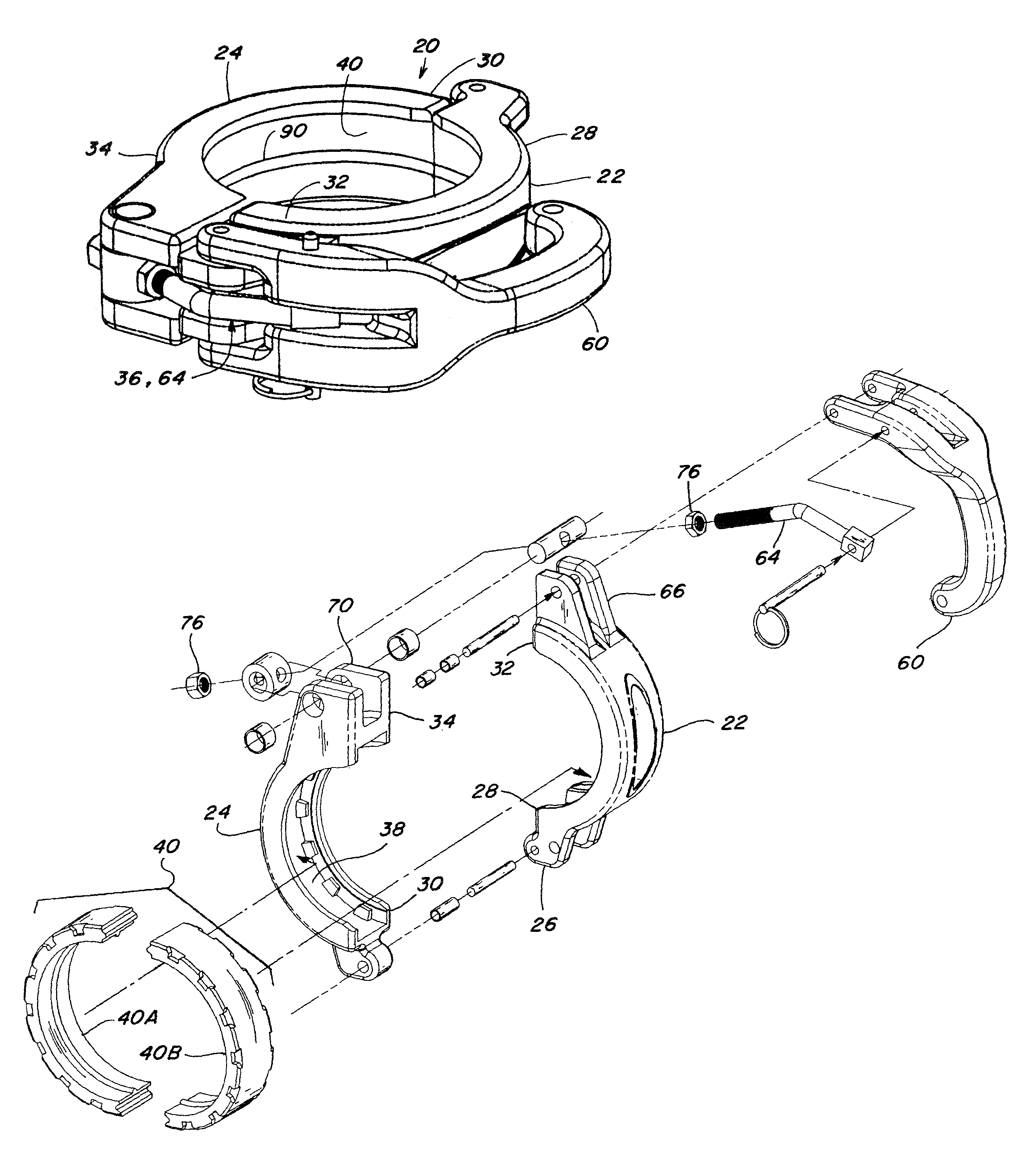
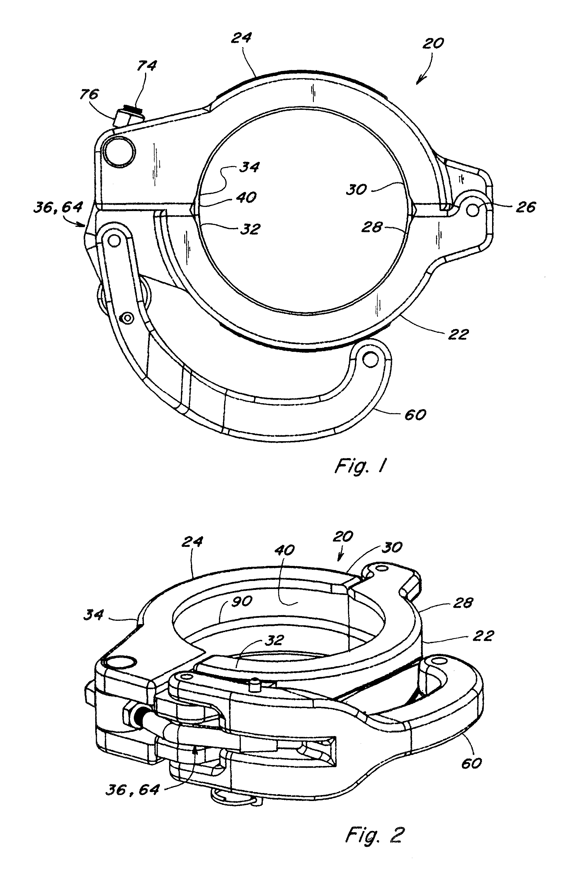
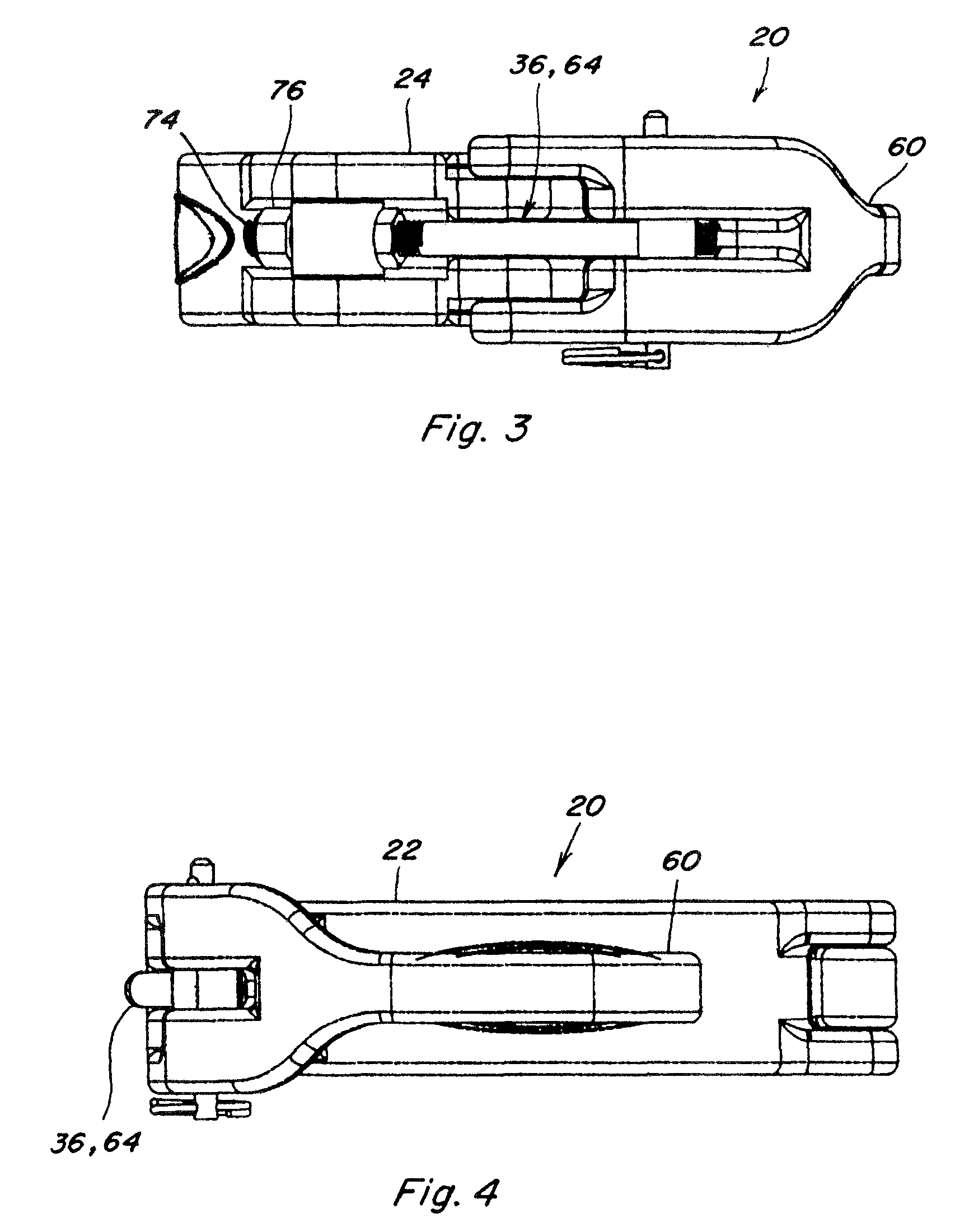
[0052]Referring to FIGS. 1 through 28, a pipe coupler 20 constructed and operable according to the teachings of the present invention, is shown. Coupler 20 includes a first semi-circular element 22, and a second semi-circular element 24, having first end portions 28 and 30, respectively, connected for relative hinged movement by a hinge joint 26. Elements 22 and 24 include second end portions 32 and 34, which are brought together when the elements are hingedly closed, and include elements of a clamping mechanism 36 operable, including with just one hand, for securing the coupler about pipe ends, or a pipe end and a fitting, to be coupled together.

[0053]Each of semi-circular elements 22 and 24 has a generally C-shaped cross-sectional shape defining a cavity 38 adapted for receiving a gasket 40. Gasket 40 is of a split configuration, here including two semi-circular gasket sections 40A and 40B, configured to be cooperatively received in cavities 38 of semi-circular elements 22 and 24,...


PUM


Abstract

A coupler for joining a pipe to another pipe, a tee, or other fitting, and more particularly, to a coupler which provides positive retention of the gasket about the circumference of the coupler sufficiently to precisely position and hold the gasket during placement about pipe ends and / or fittings to be coupled, and which provides controlled circumferential compression of the gasket during coupling, for positive sealing when the coupler is closed, while allowing one handed handling and operation during placement and coupling, such that the other hand can be used for supporting a pipe to be coupled, and which is operable for releasing and breaking loose the coupler and associated gasket from a pipe during uncoupling.

Description

[0001]This application claims the benefit of U.S. Provisional Application No. 61 / 220,692, filed Jun. 26, 2009, and U.S. Provisional Application No. 61 / 222,272, filed Jul. 1, 2009.TECHNICAL FIELD[0002]This invention relates generally to a coupler for joining a pipe to another pipe, a tee, or other fitting, and more particularly, to a coupler which provides positive retention of the gasket about the circumference of the coupler sufficiently to precisely position and hold the gasket during placement about pipe ends and / or fittings to be coupled, and which provides controlled circumferential compression of the gasket during coupling, for positive sealing when the coupler is closed, while allowing one handed handling and operation during placement and coupling, such that the other hand can be used for supporting a pipe to be coupled, and which is operable for releasing and breaking loose the coupler and associated gasket from a pipe during uncoupling.BACKGROUND ART[0003]U.S. Provisional ...

Claims


Application Information

Patent Timeline
Patent Type & Authority Patents(United States)
IPC IPC(8): F16L17/00
CPCF16L23/06F16L25/12
Inventor LINHORST, THOMAS A.HEMMAN, COREY J.LURK, MICHAEL
Owner BRAY INT INC
Why Eureka
Try Eureka