Medical device

a technology of medical devices and endoscopes, applied in the field of medical devices, can solve the problems of difficult to bring the distal end of an endoscope to a position near the target site in a short period of time with accuracy

Active Publication Date: 2012-06-19
OLYMPUS CORP
View PDF23 Cites 63 Cited by
  • Summary
  • Abstract
  • Description
  • Claims
  • Application Information

AI Technical Summary

Problems solved by technology

In a tract such as bronchus in a body that is branched in multiple steps, in a case where a diseased area is located at the end of a bronchus, it is hard to bring the distal end of an insertion section of an endoscope to a position near the target site in a short period of time with accuracy.

Method used


Image

  • Medical device
  • Medical device
  • Medical device

Examples


first embodiment

[0041]Now, with reference to the drawings, a medical device 1 of a first embodiment according to the present invention will be explained below.

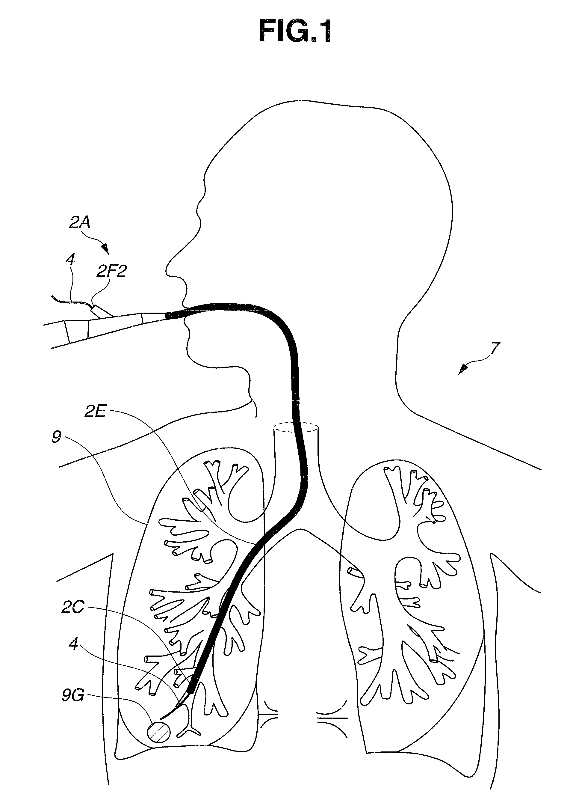
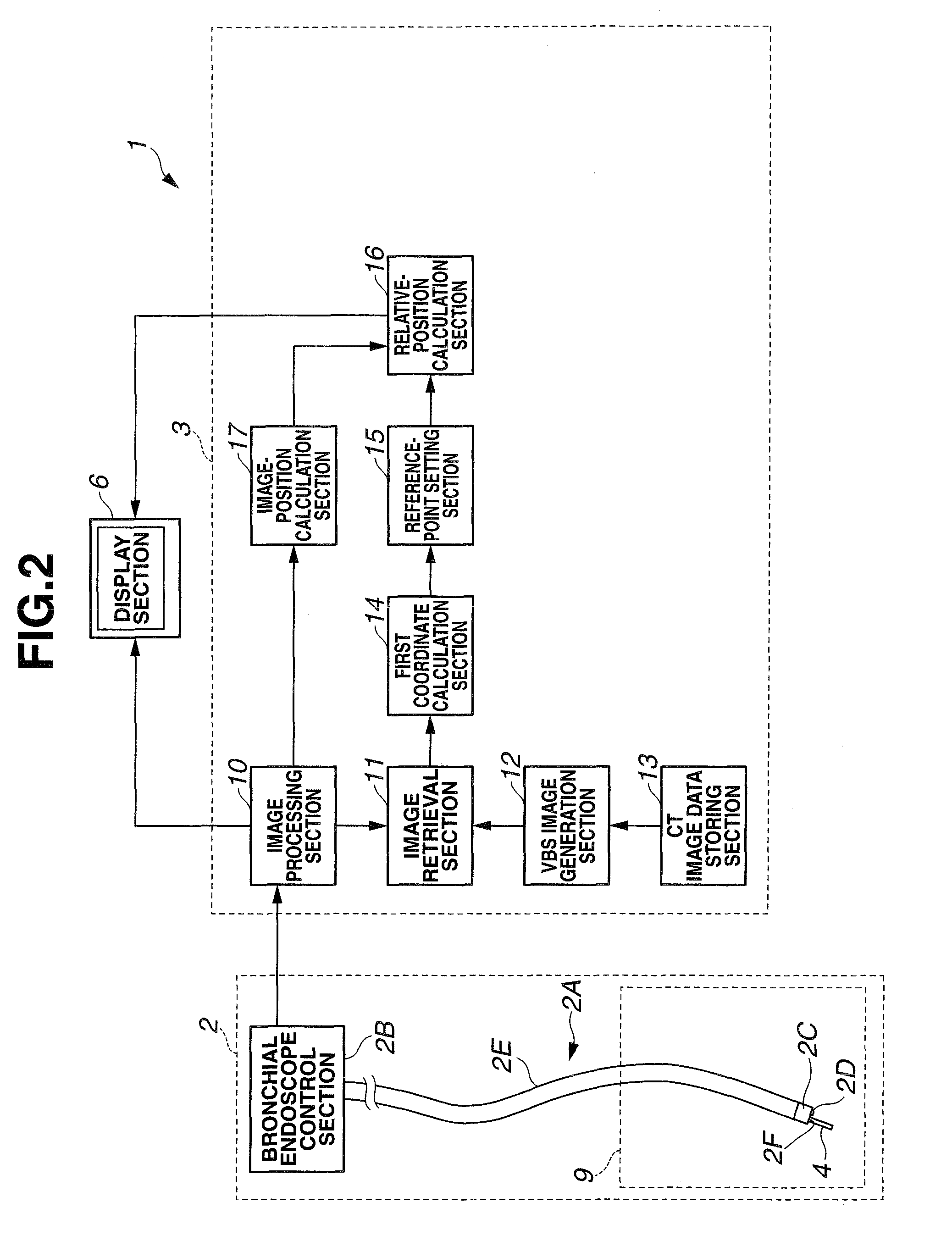
[0042]FIG. 1 is an illustrative view of a state in which an examination or treatment of a target site 9G at a bronchus 9 in a patient 7 with a medical instrument inserted through a channel 2F1 of an endoscope 2A is being performed, and FIG. 2 is a configuration view showing a configuration of the medical device 1 of an embodiment according to the present invention.

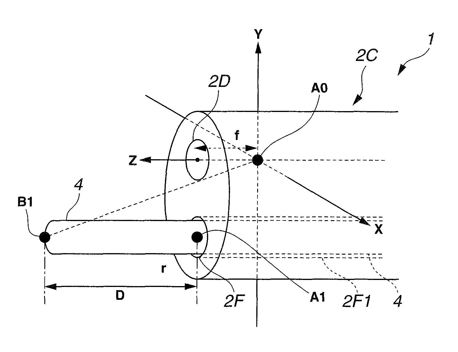
[0043]FIG. 1 shows a state where a distal end portion 2C of an insertion section 2E is being inserted into a tract having the minimal diameter for insertion of the distal end portion 2C in the bronchus 9. A treatment instrument 4 that is a medical instrument having a small diameter and is inserted through the channel 2F1 from a treatment instrument insertion port 2F2 is protruded out of the distal end portion 2C of the endoscope 2A, and samples the tissues of the target site 9G.

[004...

modified example 1 of first embodiment

[0074]FIGS. 7A to 7C are illustrative views showing a method for calculating a relative position between the reference point A1 and the treatment instrument 4 in a medical device 1B according to a modified example 1 of the first embodiment: FIG. 7A is a perspective view showing inside of the bronchus 9; FIG. 7B shows an endoscopic image; and FIG. 7C is a perspective view illustrating the relationship between the treatment instrument 4 and the distal end portion 2C. The medical device 1B is similar to the medical device 1, and the same components thereof are denoted by the same reference numerals, which will not be explained below.

[0075]As shown in FIG. 7B and FIG. 7C, the medical device 1B is provided with a marker M1 arranged at the distal end portion of the treatment instrument 4 in advance. The marker M1 is preferably arranged at a position which is in the up direction when the medical device 1B is bended, so that the position of the marker M1 can be easily checked in an endoscop...

modified example 2 of first embodiment

[0078]FIGS. 8A to 8C are illustrative views showing a method for calculating a relative position between the reference point A1 and the treatment instrument 4 in a medical device 1C according to a modified example 2 of the first embodiment: FIG. 8A is a perspective view showing inside of the bronchus 9; FIG. 8B shows an endoscopic image; and FIG. 8C is a perspective view illustrating the relationship between the treatment instrument 4 and the distal end portion 2C. The medical device 1C is similar to the medical devices 1 and 1B, and the same components thereof are denoted by the same reference numerals, which will not be explained below.

[0079]As shown in FIG. 8B and FIG. 8C, the medical device 1C is provided with two markers M1 and M2 arranged on the center line of the distal end portion of the treatment instrument 4 in advance. The medical device 1C having the treatment instrument 4 with two markers M1 and M2 is able to calculate the relative position of the treatment instrument 4...


PUM


Abstract

A medical device for examination or treatment based on a reference point, includes: a virtual endoscopic image generation section configured to generate a virtual endoscopic image of a bronchus from a plurality of different line-of-sight positions using three-dimensional image data of the bronchus of a subject that is obtained in advance; an image retrieval section configured to retrieve a virtual endoscopic image highly similar to an endoscopic image of the bronchus picked up by an image pickup section arranged at a distal end portion of an insertion section; a reference-point setting section configured to set a reference point based on a line-of-sight position of the highly similar virtual endoscopic image; and a relative-position calculation section configured to calculate a relative position of a treatment instrument to the reference point.

Description

[0001]This application claims benefit of Japanese Application No. 2008-135633 filed in Japan on May 23, 2008, the contents of which are incorporated by this reference.BACKGROUND OF THE INVENTION[0002]1. Field of the Invention[0003]The present invention relates to a medical device having an image pickup section that is able to pick up images of a tube cavity in a subject, more particularly, to a medical device that performs examination or treatment with high accuracy using virtual endoscopic images of a tube cavity based on three-dimensional image data of a subject.[0004]2. Description of the Related Art[0005]In recent years, diagnoses have been widely made using three-dimensional images. For example, a diagnosis for a target site can be made using three-dimensional image data of a subject which is obtained by picking up tomographic images of the subject with an X-ray CT (Computed Tomography) apparatus.[0006]In the CT apparatus, a subject is continuously moved while X-ray radiating p...

Claims


Application Information

Patent Timeline
Patent Type & Authority Patents(United States)
IPC IPC(8): A61B1/00A61B1/06
CPCA61B1/00009A61B1/267A61B5/064A61B5/065A61B1/00133A61B19/5244A61B34/20
Inventor ITO, SEIICHIAKIMOTO, SHUNYAONISHI, JUNICHISUZUKIIKUMA, SOICHI
Owner OLYMPUS CORP
Why Eureka
Try Eureka