Induction heating appliance for cooking

a technology for induction heating appliances and cooking containers, which is applied in the direction of induction heating, electric/magnetic/electromagnetic heating, electrical apparatus, etc., can solve the problems of inability of infrared sensors to detect the temperature of cooking containers properly, the position of infrared sensors is hardly ascertained with eyes, and the infrared sensors are not properly detected. to achieve the effect of increasing the usability of induction heating appliances

Inactive Publication Date: 2012-06-19
PANASONIC CORP
View PDF14 Cites 12 Cited by
  • Summary
  • Abstract
  • Description
  • Claims
  • Application Information

AI Technical Summary

Benefits of technology

[0007]The induction heating appliance for cooking according to the present invention includes an infrared permeable window defined inwardly of an infrared sensor display window and surrounded by a light shielding element so as to have a size narrower than the infrared sensor display window, and an infrared sensor disposed beneath the infrared permeable window for detecting infrared radiation emanating from the cooking container. Since the infrared permeable window allows infrared rays of light to pass therethrough and is provided only on an upper region of the infrared sensor, not only can any undesirable reduction in level of detecting the infrared rays of light emanating from the cooking container such as, for example, a pan, which would otherwise occur when strong ambient light around the induction heating appliance enters the infrared sensor be avoided, but also the infrared sensor display window can be presented large in size to the user to enable him or her to recognize the position of the infrared sensor. Also, even when the cooking container displaces somewhat from the infrared sensor display window, the upper region of the infrared permeable window provides an additional coverage for which the cooking container can cover it and, as a result, the temperature control can be performed stably notwithstanding the displacement of the cooking container, thus resulting in an increase in usability of the induction heating appliance.
[0008]Furthermore, with the light emitting element, the position of the infrared sensor can be indicated visually so that the user can assuredly place the cooking container such as, for example, a pan at the position at which the permeable windows for the infrared sensor can be covered. Particularly where the environment is dark, it is indeed effective to provide a visual indication of the position of the infrared sensor by means of the light emitting element.

Problems solved by technology

It has, however, been found that in the induction heating appliance for cooking of the structure discussed above, the infrared sensor fails to properly detect the temperature of a cooking container if the user unwittingly fails to place such cooking container in such a manner as to cover an upper surface region of the infrared sensor.
Particularly where the environment around the induction heating appliance is dark, there is a problem that the position of the infrared sensor is hardly ascertained with eyes.
Although the induction heating appliance for cooking, which is good in temperature follow-up characteristic, can be made available if the infrared sensor is arranged in proximity to that portion of the heating coil winding, the infrared sensor in such case tends to be arranged at a location offset from the center of the heating coil and, therefore, the possibility would come to be high that the user will not place the cooking container above the infrared sensor, thus resulting in a failure of the infrared sensor to detect the temperature of the cooking container properly.

Method used


Image

  • Induction heating appliance for cooking
  • Induction heating appliance for cooking
  • Induction heating appliance for cooking

Examples


first embodiment

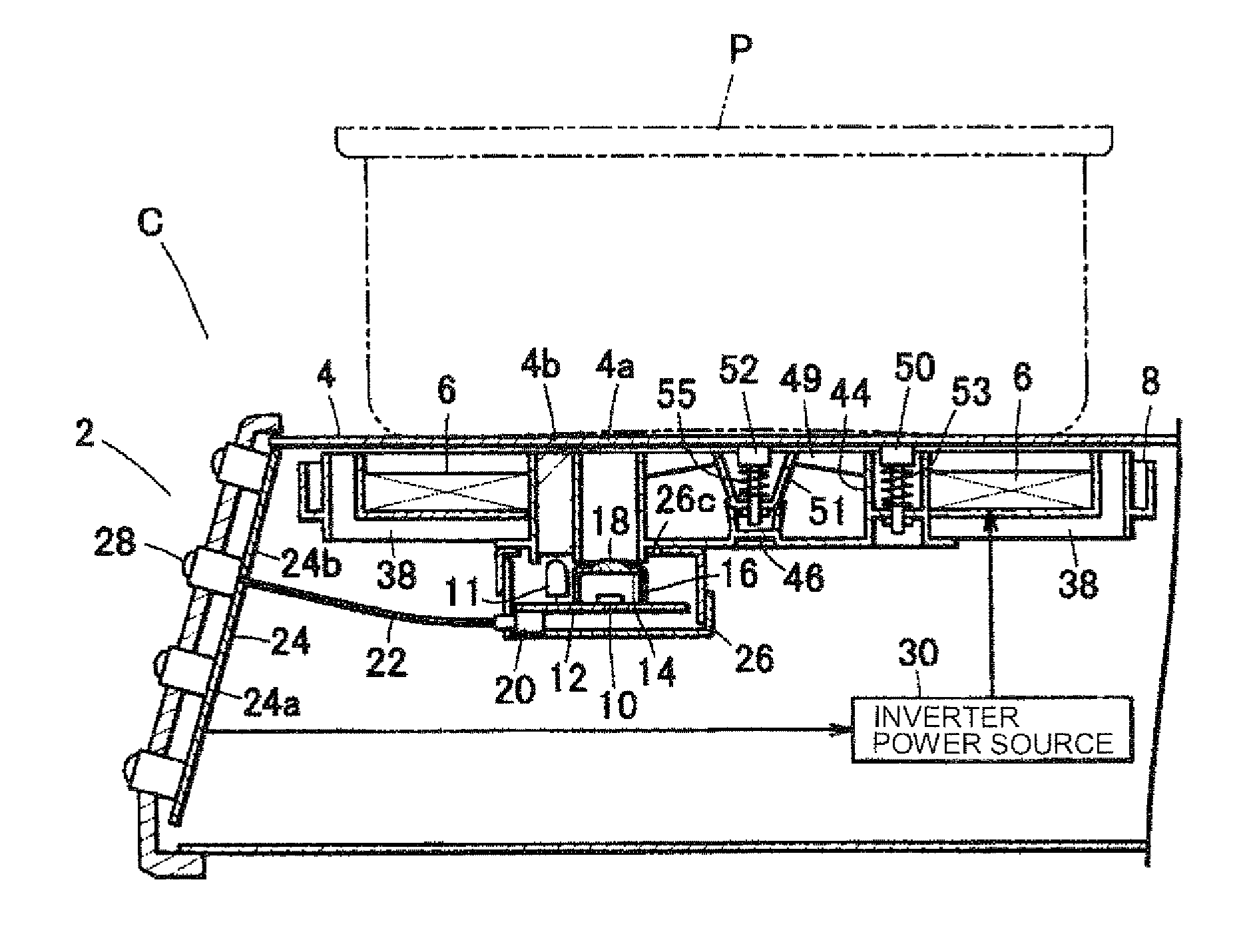
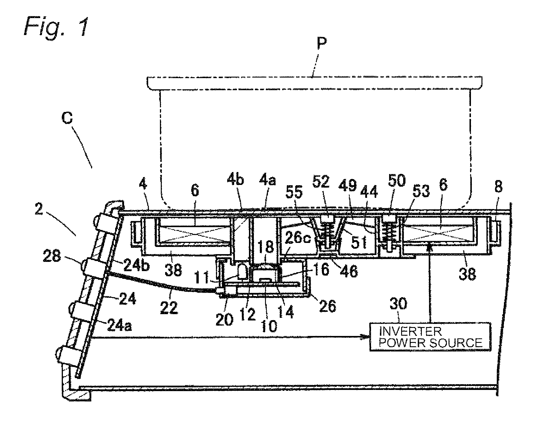
[0027]FIG. 1 illustrates, in a schematic sectional representation, an induction heating appliance C for cooking according to a first preferred embodiment of the present invention. As best shown in FIG. 1, the induction heating appliance C of the present invention includes a body 2 forming an outer shell, a top plate 4 mounted on a top area of the body 2 to place thereon a cooking container P such as, for example, a pan, and a generally disc-shaped heating coil 6 arranged beneath the top plate 4 for generating high frequency magnetic fields.

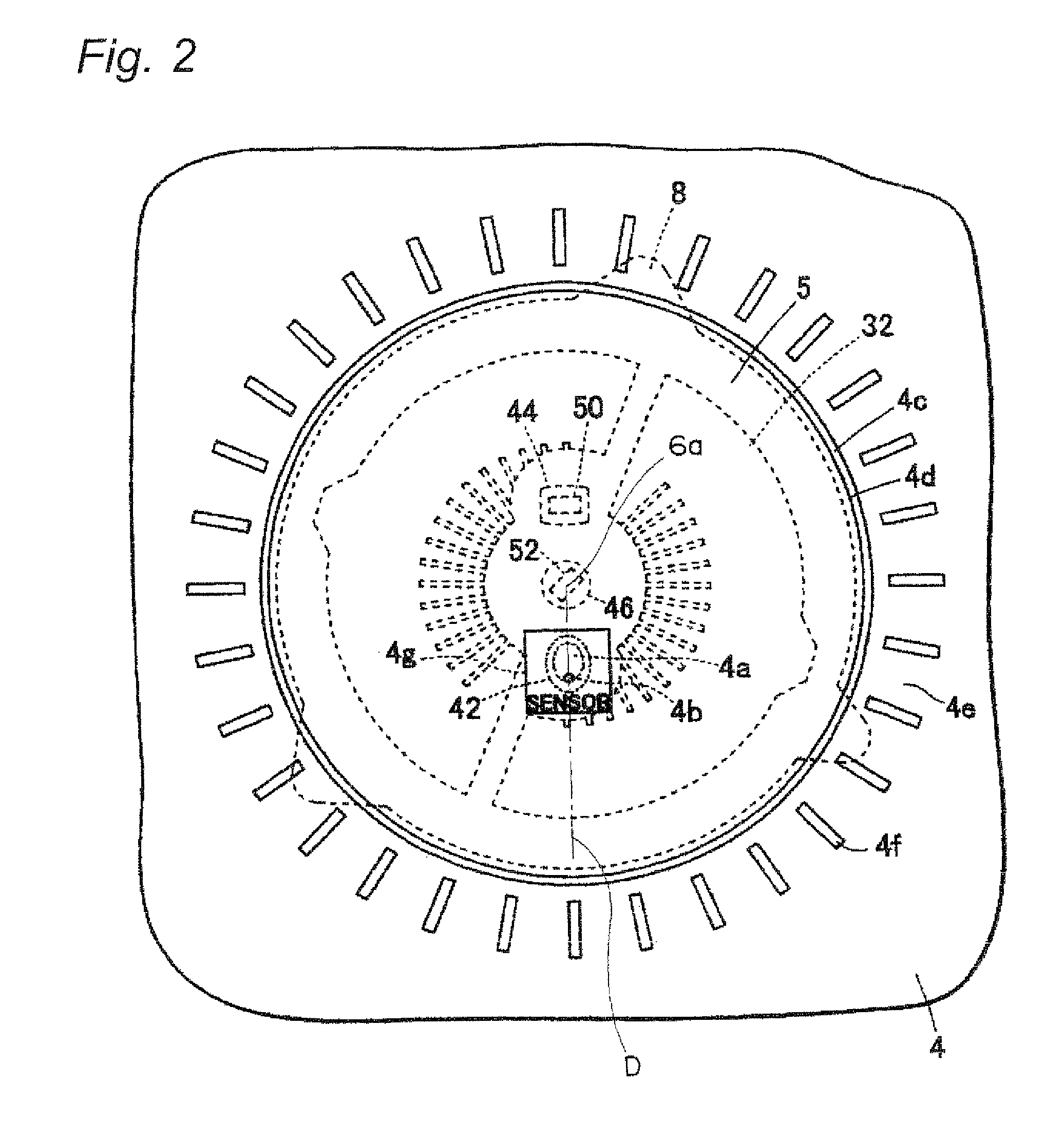
[0028]The top plate 4 referred to above is made of a light transmissible, insulating material such as, for example, crystallized ceramic and is formed into a plate shape. The top plate 4 has a table top surface, or a rear surface opposite to the table top surface, provided with a heating area 5, the perimeter of which is indicated to show where a cooking container P has to be placed (see FIG. 2). The heating area 5 is defined by a colored, for exa...

second embodiment

[0072]FIG. 7 illustrates a fragmentary top plan view showing the top plate employed in the induction heating appliance for cooking according to a second preferred embodiment of the present invention. FIG. 8 illustrates a fragmentary enlarged diagram showing the infrared sensor and its vicinity in the induction heating appliance for cooking. Component parts referred to hereinafter, but similar to those employed in the previously described embodiment of the present invention are designated by like reference numerals and, therefore, the details thereof are not reiterated for the sake of brevity.

[0073]Referring now to FIG. 7, a center front portion of the top plate 4 showing the heating area 5 has its rear surface provided with the black colored, printed thin film 7c (see FIG. 8) capable of transmitting light therethrough and formed with the infrared sensor display window 4g and represents a generally rectangular shape when viewed from above. In FIG. 8, a region indicated by A represent...

third embodiment

[0076]FIG. 9 illustrates a fragmentary top plan view of the top plate employed in the induction heating appliance according to a third preferred embodiment of the present invention. FIG. 10 is a fragmentary enlarged view showing the infrared sensor and its vicinity in the induction heating appliance shown in FIG. 9. Component parts referred to hereinafter, but similar to those employed in the previously described embodiment of the present invention are designated by like reference numerals and, therefore, the details thereof are not reiterated for the sake of brevity.

[0077]Referring to FIG. 9, the rear surface of the top plate 4, which shows the presence of the heating area 5, has a black colored, printed thin film 7c (see FIG. 10) capable of passing light therethrough, which is provided over substantially the entire surface thereof. On the other hand, the table top surface of the top plate 4 opposite to the rear surface referred to above is formed with an infrared sensor display wi...


PUM


Abstract

An infrared permeable window 4a, which is surrounded by a light shielding layer 7b and is narrower than an infrared sensor display window 4g, is formed inwardly of the infrared sensor display window 4g, and an infrared incident area 43a for detecting infrared rays of light and a light emitting unit 56a are provided below the infrared permeable window 4a. Also, a light emitting surface 4b is provided inwardly of the infrared permeable window 4a, so that the user can assuredly place a cooking container P on the infrared permeable window 4a.

Description

TECHNICAL FIELD[0001]The present invention relates to an induction heating appliance for cooking operable to heat a cooking container by electromagnetic induction, in which an infrared sensor is utilized to control the temperature of the cooking container.BACKGROUND ART[0002]In recent years, the use of induction heating appliances as fireless cooking devices for cooking has been widely spreading. This type of induction heating appliance for cooking includes an infrared sensor disposed below a center portion of a heating coil and a control unit operable in response to an output from the infrared sensor to control an inverter circuit to thereby control the output of the heating coil (see, for example, Japanese Laid-open Patent Publication No. 2005-38660).SUMMARY OF THE INVENTION[0003]It has, however, been found that in the induction heating appliance for cooking of the structure discussed above, the infrared sensor fails to properly detect the temperature of a cooking container if the...

Claims


Application Information

Patent Timeline
Patent Type & Authority Patents(United States)
IPC IPC(8): H05B6/12
CPCH05B6/062H05B6/1209H05B2213/07
Inventor KATAOKA, AKIRAKEISHIMA, TOSHIHIROMORIMOTO, YASUSHI
Owner PANASONIC CORP
Why Eureka
Try Eureka