Eddy current probes having magnetic gap

a magnetic gap and probe technology, applied in the field of probes, can solve the problems of difficult to limited physical characteristics, and special damage to the two ends of the nuclear fuel rod, so as to reduce the mutual induction, reduce the size of the probe, and high discriminability

Inactive Publication Date: 2012-06-19
INST NUCLEAR ENERGY RES ROCAEC
View PDF8 Cites 2 Cited by
  • Summary
  • Abstract
  • Description
  • Claims
  • Application Information

AI Technical Summary

Benefits of technology

[0007]The fourth purpose of the present invention is to provide the probe with reduced mutual induction between coils to obtain high discriminability. With reduced probe size owing to shorten distances between coils, while the probe is able to move easily inside and outside the tubal object.
[0008]The fifth purpose of the present invention is to provide the probe for detection having a high Q value with reduced coil number around a high flux magnetic core and reduced coil internal resistance.

Problems solved by technology

Yet some physical characteristics, like edge effect, are limited in some cases.
For example, a nuclear fuel rod may be especially damaged at two ends of the rod.
Its magnetic field affects a big area; distances between coils are widened to avoid mutual induction, and thus probe size is hard to be reduced in size.
Since the probe is not reduced in size, detection for the tubal object is limited.
In addition owing to the mutual induction between the coils on moving the probe along the tubal object, signals of measurement may not be exactly received and discriminability is thus lowered.
Hence, the prior art does not fulfill all users' requests on actual use.

Method used


Image

  • Eddy current probes having magnetic gap
  • Eddy current probes having magnetic gap
  • Eddy current probes having magnetic gap

Examples


Embodiment Construction

[0017]The following descriptions of the preferred embodiments are provided to understand the features and the structures of the present invention.

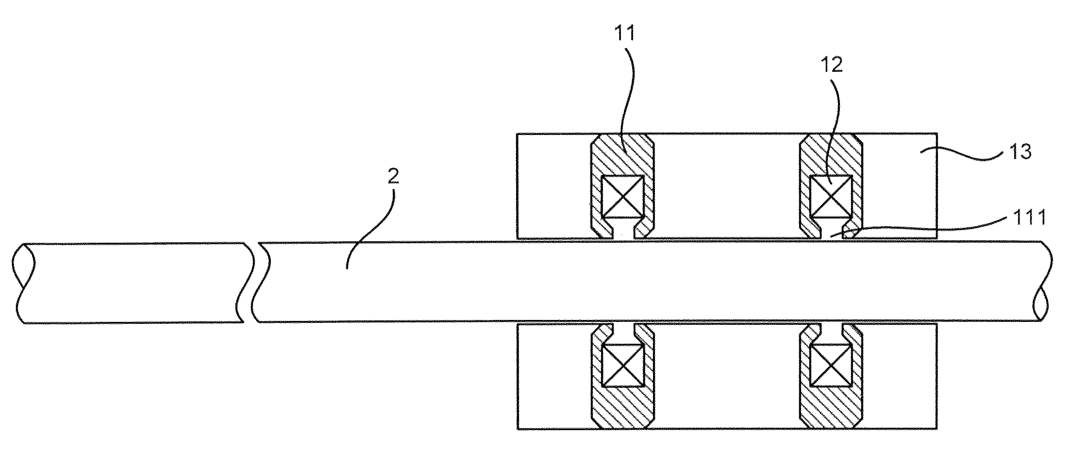
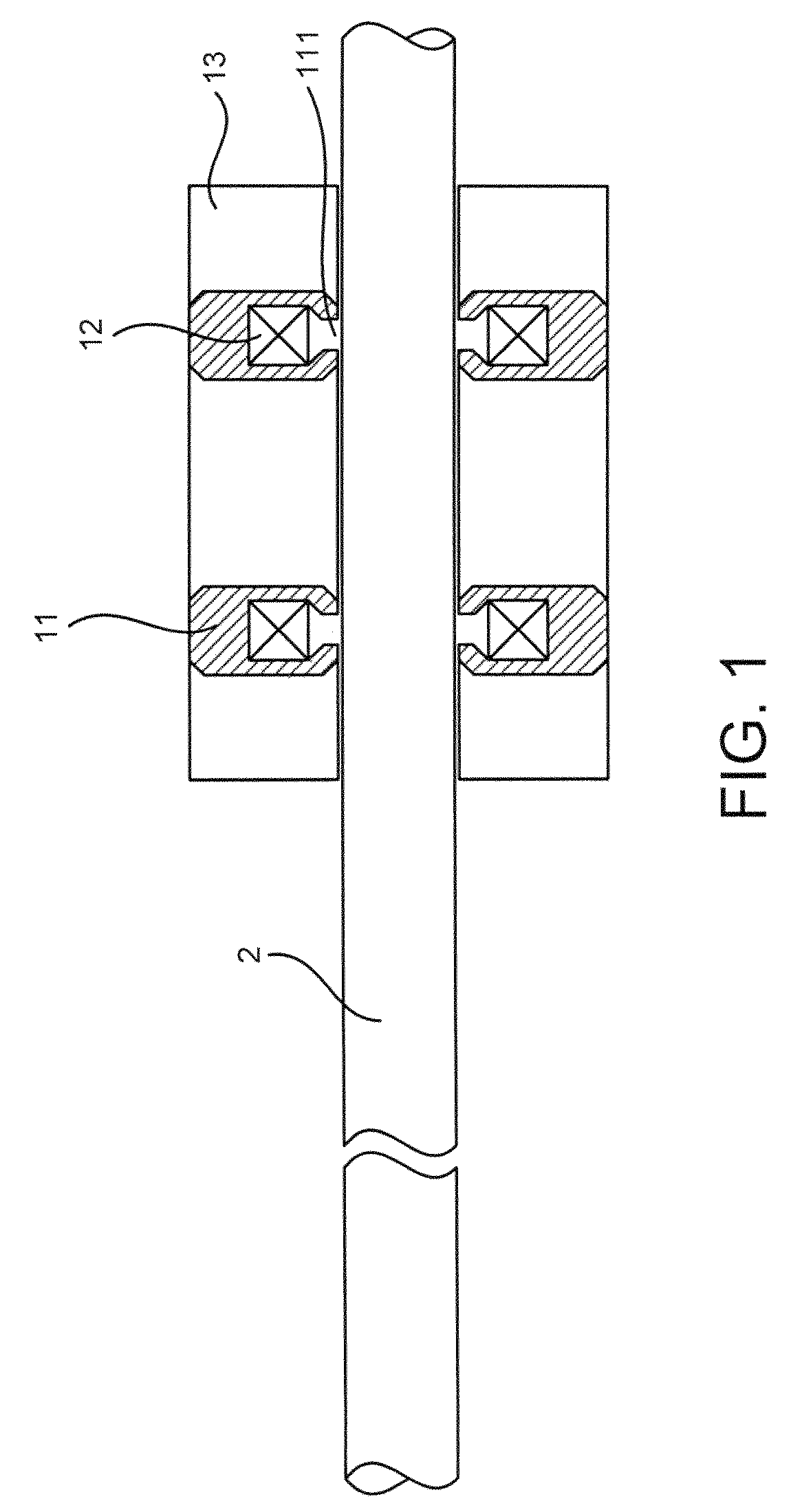
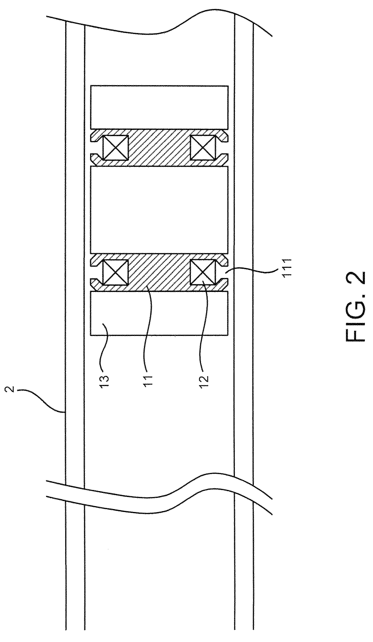
[0018]Please refer to FIG. 1 to FIG. 3, which are views showing a first and a second preferred embodiments according to the present invention; and a view showing an equivalent circuit. As shown in the figures, the present invention is an eddy current probe having a magnetic gap, comprising a high flux magnetic core 11, an excitatory coil 12, a support part 13 and a detection part 14, where a tubal object 2 is detected at an outside surface, an inside surface or an end of the tubal object 2.

[0019]The high flux magnetic core 11 has a U-shape and surrounds the tubal object 2, where the high flux magnetic core 11 has an annular gap 111 at a face facing the tubal object 2.

[0020]The excitatory coil 12 winds around the high flux magnetic core 11; and generates an eddy current in the tubal object 2 by a part of the excitatory coil 12 revealed towa...


PUM

PropertyMeasurementUnit
eddy current probeaaaaaaaaaa
magnetic gapaaaaaaaaaa
frequencyaaaaaaaaaa

Abstract

An eddy current probe uses magnetic gap. The probe has a small size; and coil number in the probe is reduced. Hence, the probe can move easily inside and outside a tube and detect an end of the tube as close as possible.

Description

FIELD OF THE INVENTION [0001]The present invention relates to a probe; more particularly relates to providing a particular magnetic field lines loop to limit a magnetic field by a magnetic gap for obtaining high resolution and small size probe to move easily inside and outside a tubal object.DESCRIPTION OF THE RELATED ARTS [0002]In FIG. 4 and FIG. 5, general eddy current probes include absolute-type probes and differential-type probes. Coils wind around an air-cored probe and the probe is put on an outside or inside surface of a tubal object. Yet some physical characteristics, like edge effect, are limited in some cases. For example, a nuclear fuel rod may be especially damaged at two ends of the rod.[0003]Moreover, the air-cored probe has many circle coils and thus internal resistance of the coils 3 is high, where an equivalent circuit of the probe is shown in FIG. 6. Its magnetic field affects a big area; distances between coils are widened to avoid mutual induction, and thus prob...

Claims


Application Information

Patent Timeline
Patent Type & Authority Patents(United States)
IPC IPC(8): G01N27/72
CPCG01N27/902G01R33/12
Inventor PENG, KANG-NENGLIU, CHING-SHIHHWANG, KANG-LIN
Owner INST NUCLEAR ENERGY RES ROCAEC
Why Eureka
Try Eureka