Autonomous ultrasonic indoor location system, apparatus and method

an indoor location and ultrasonic technology, applied in the field of indoor location and position sensing, can solve the problems of inability to deploy and administer a system in a scalable way, inability to guarantee user privacy, and inability to work well with gps, etc., to achieve convenient scalable in practical application scenarios, low system complexity, and high location accuracy

Active Publication Date: 2012-06-19
NEC (CHINA) CO LTD
View PDF25 Cites 31 Cited by
  • Summary
  • Abstract
  • Description
  • Claims
  • Application Information

AI Technical Summary

Benefits of technology

[0011]In order to solve the above problems, it is an object of the present invention to provide an indoor location system that is user-privacy preserving, decentralized, high accuracy and low-cost for practical application scenarios. An autonomous ultrasonic indoor location system includes a location beacon transmitting apparatus and a location beacon receiving apparatus. The location beacon transmitting apparatus is configured to sequentially transmit US signals at a predetermined time interval upon transmission of a signal containing synchronization information. The location beacon receiving apparatus is configured to synchronize with the location transmitting apparatus when synchronization information is detected, determine transmission order of the received US signals based on the obtained synchronization timing, infer transmission timings of the respective US signals based on the determined transmission order, calculate TOA information corresponding to each of the received US signal from the transmission timings and reception timings of the respective US signals, and determine location of the location beacon receiving apparatus on basis of the positions of the US transmitters in the transmitting apparatus and the calculated TOA information sequence.
[0018]As compared with the prior art, the autonomous ultrasonic indoor location system presented in the present invention brings the advantages of low system complexity, user-privacy preserving, high location accuracy and real-time.
[0019]The indoor location system of the invention provides a simple mechanism for transmitting location beacons and is capable of coordinating transmission of synchronization information and transmission of US signals for position calculation in a simplified way.
[0020]The indoor location system of the present invention performs position calculation at the receiver side without the necessity to provide a central server for control and maintenance, and is readily scalable in practical application scenarios.

Problems solved by technology

The well-known Global Positioning System (GPS) can provide the object's location information at the accuracy of several ten meters outdoors, however, in indoor environment GPS does not work well since the positioning result of GPS is degraded dynamically by multipath effect and signal obstruction.
In this case, a database kept track of the locations of all the entities, thereby the user privacy may not be guaranteed.
Further, in a tracking system, all control and management functions are centralized at the server side so that it is not possible to deploy and administer a system in a scalable way.
However, RF (radio-frequency) systems, which use signal strength to estimate location can not yield satisfactory results because RF propagation within buildings deviates heavily from empirical mathematical models.
However, there are disadvantages of Cricket system: 1) multiple RF transmission and multiple US transmission are employed in Cricket system so as to make the coordination rather complex and to increase the system cost; 2) since the RF transmitters are randomly selected such that only one ULB transmitter may emit RF and US signal at a time, the RF emission from all ULB transmitters are unordered; and 3) an Object hears only one ultrasonic beacon at a time, and may move between chirps from different beacons.
As a result, there is no guaranteed simultaneity in the distance samples, which can lead to inaccurate position estimation.

Method used


Image

  • Autonomous ultrasonic indoor location system, apparatus and method
  • Autonomous ultrasonic indoor location system, apparatus and method
  • Autonomous ultrasonic indoor location system, apparatus and method

Examples


Embodiment Construction

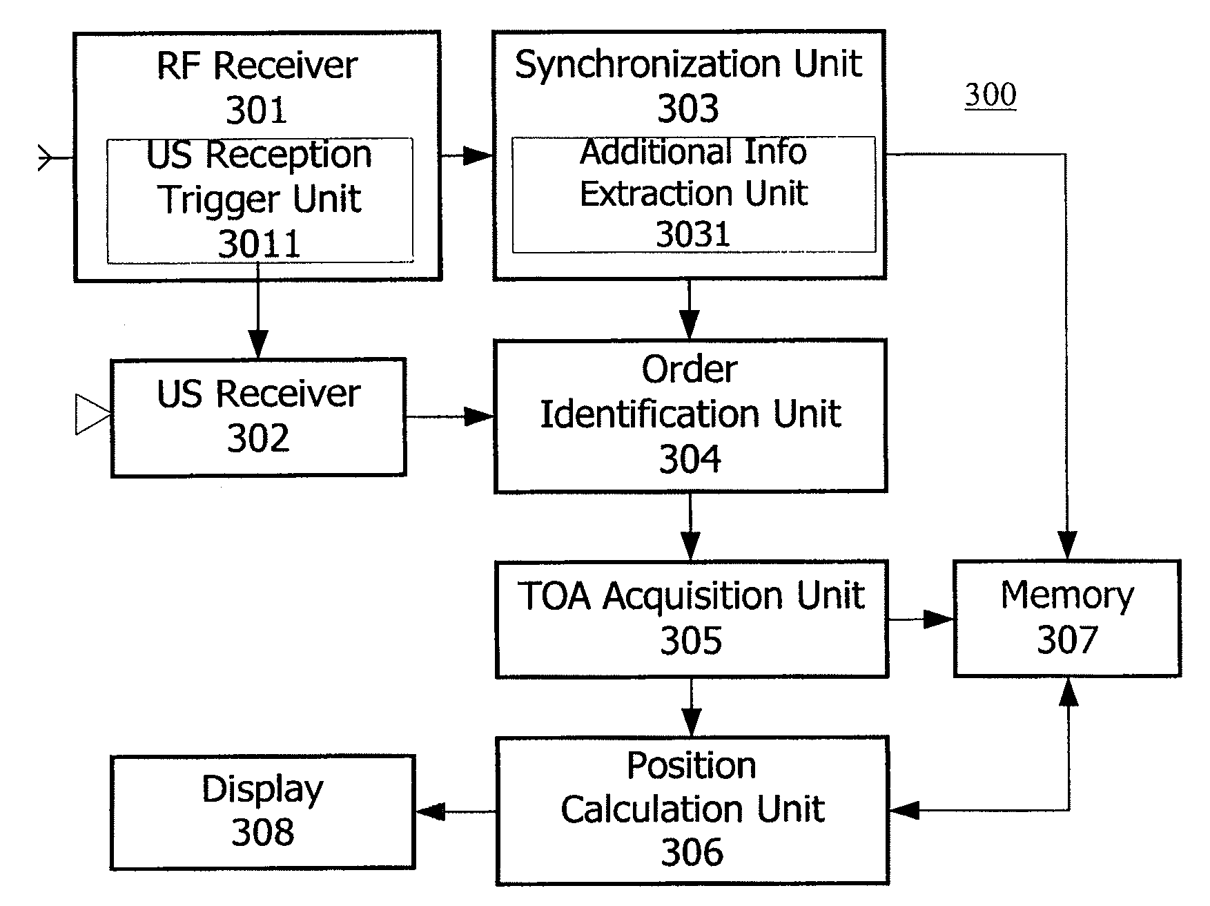
[0036]Embodiments of the present invention will be described below with reference to the accompanying drawings. In the description herein, numerous specific details are provided, such as examples of components and / or methods, to help fully understanding of the present invention. However, it will be appreciated by those skilled in the art that embodiments of the present invention may be implemented without one or more of these specific details or with other apparatus, system, assembly, method, component, material, element, etc. In other instances, well known structure, material or operation have not been depicted or described in detail in order not to obscure aspects of the embodiments of the present invention. In this specification and drawings, like reference numerals represent structural elements with substantially the same functions, and repeated description of them will be omitted.

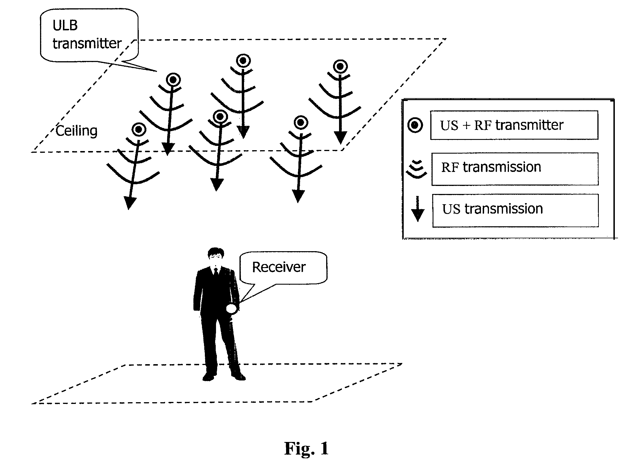
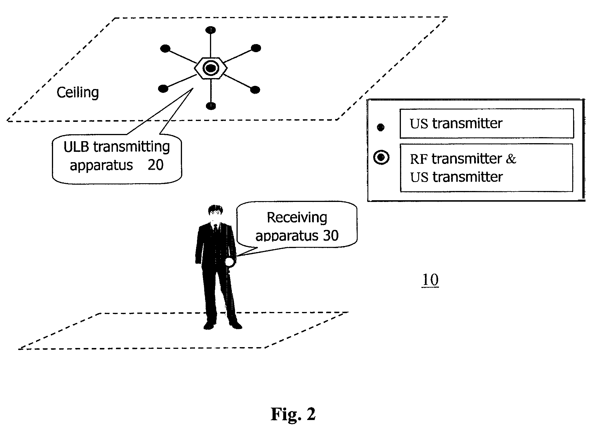
[0037]Firstly, overview of an ultrasonic based location system according to an embodiment of the pr...


PUM


Abstract

An autonomous ultrasonic indoor location system includes a location beacon transmitting apparatus and a location beacon receiving apparatus. The location beacon transmitting apparatus is configured to sequentially transmit US signals at a predetermined time interval upon transmission of a signal containing synchronization information. The location beacon receiving apparatus is configured to synchronize with the location transmitting apparatus when synchronization information is detected, determine transmission order of the received US signals based on the obtained synchronization timing, infer transmission timings of the respective US signals based on the determined transmission order, calculate TOA information corresponding to each of the received US signal from the transmission timings and reception timings of the respective US signals, and determine location of the location beacon receiving apparatus on basis of the positions of the US transmitters in the transmitting apparatus and the calculated TOA information sequence.

Description

TECHNICAL FIELD[0001]The technical field of the present invention relates to indoor location and position sensing, and in particular, to an ultrasonic based indoor location system, apparatus and method that performs position calculation at client side and lets the objects know their own physical position.BACKGROUND[0002]Undoubtedly, location information is a fundamental content to be utilized to extract the geographical relationship between the users and the environments so as to further understand the user behaviors. The importance Is and promise of location-aware applications has led to the design and implementation of systems for providing location information, particularly in indoor and urban environments. Currently, there is an increasing market need for high-accuracy tracking of people and assets in real time in many different application scenarios including office, healthcare, coalmine, subway, smart building, restaurant etc. For instance, in office environment, employees are...

Claims


Application Information

Patent Timeline
Patent Type & Authority Patents(United States)
IPC IPC(8): G01S3/80
CPCG01S11/16G01S5/30
Inventor ZHAO, JUNHUIWANG, YONGCAI
Owner NEC (CHINA) CO LTD
Why Eureka
Try Eureka