
Image forming apparatus and method for detecting the fullness of waste-toner container

a technology waste-toner container, which is applied in the direction of electrographic process apparatus, instruments, optics, etc., can solve the problems of user misconcern of image forming apparatus malfunction or failure, and the inside of the image forming apparatus becomes dirty, etc., to achieve the effect of sufficient reduction of production costs

Active Publication Date: 2012-06-19
KYOCERA DOCUMENT SOLUTIONS INC
View PDF3 Cites 4 Cited by
  • Summary
  • Abstract
  • Description
  • Claims
  • Application Information

AI Technical Summary

Benefits of technology

[0011]An advantage of the present invention is that, while obtaining a sufficient reduction in production costs when the fullness of the waste-toner container is detected, it maintains the image forming apparatus in a non-printable state until the waste-toner container is replaced, and prevents a user from mistakenly believing the apparatus is malfunctioning.

Problems solved by technology

If the waste toner continues to be sent to the waste-toner container after the container is full, the member used to convey the waste toner (for example, a conveying screw or a conveying tube) can be damaged or the waste toner, that is unable to be stored in the container, can spill during the replacement of the waste-toner container, which may cause a problem in that the inside of the image forming apparatus becomes dirty.
However, because the waste toner is in powder form, a cone-shaped pile of the waste toner deposited in the waste-toner container may collapse because of: vibrations applied to the image forming apparatus during printing; new waste toner that is added to the waste-toner container; weight of the waste toner and the like.
This leads to a problem in that a user may misconceive that the image forming apparatus is malfunctioning or failed.
The image forming apparatus set forth above does not have a countermeasure to be taken when the deposited pile of the waste toner collapses, and thus, is unable to solve the above-described problem.
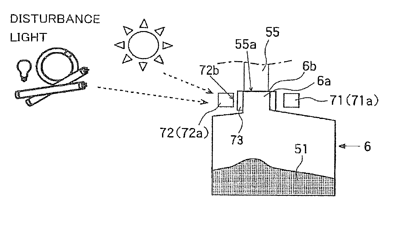
However, with the image forming apparatus, if the cover for the replacement of the waste-toner container is opened, the fullness of the waste-toner container cannot be accurately detected because of outside light, such as illumination light or solar light.
Accordingly, the image forming apparatus requires a switch, or the like, to detect whether or not the cover is open, and thus, the reduction in production costs is insufficient.
However, because it is impossible to clearly distinguish the situation where the waste-toner container is full and the situation where the bottle is not attached, detection performance is insufficient.
When the control unit has determined that the waste-toner container is full, by referencing the output voltage of the light-receiving portion and the storage unit, the control unit prohibits printing and does not permit the image forming apparatus to perform printing until the control unit detects that the light-blocking member is projected, the light-blocking member is then retracted, and the waste-toner container is not full.

Method used


Image

  • Image forming apparatus and method for detecting the fullness of waste-toner container
  • Image forming apparatus and method for detecting the fullness of waste-toner container
  • Image forming apparatus and method for detecting the fullness of waste-toner container

Examples


Embodiment Construction

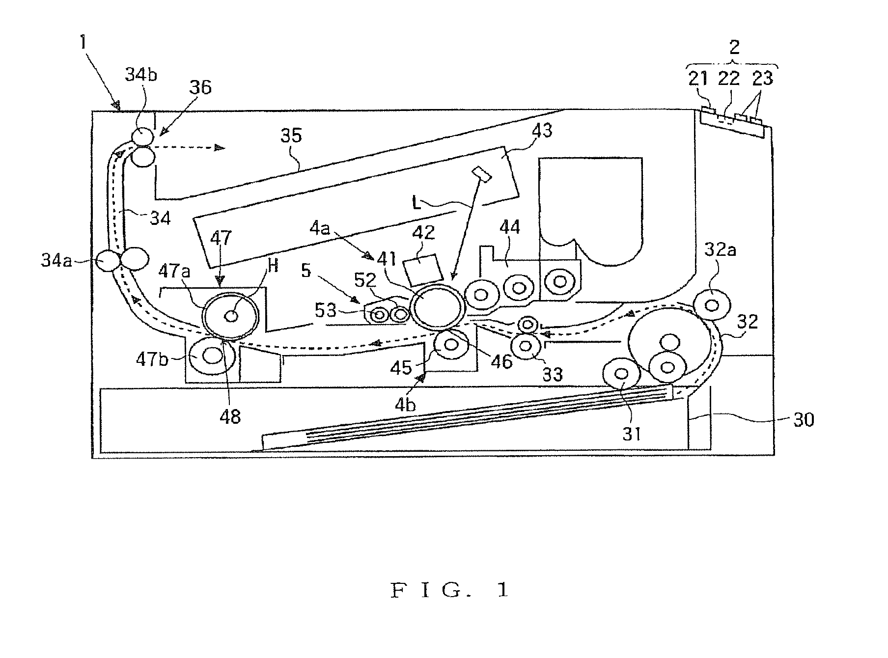
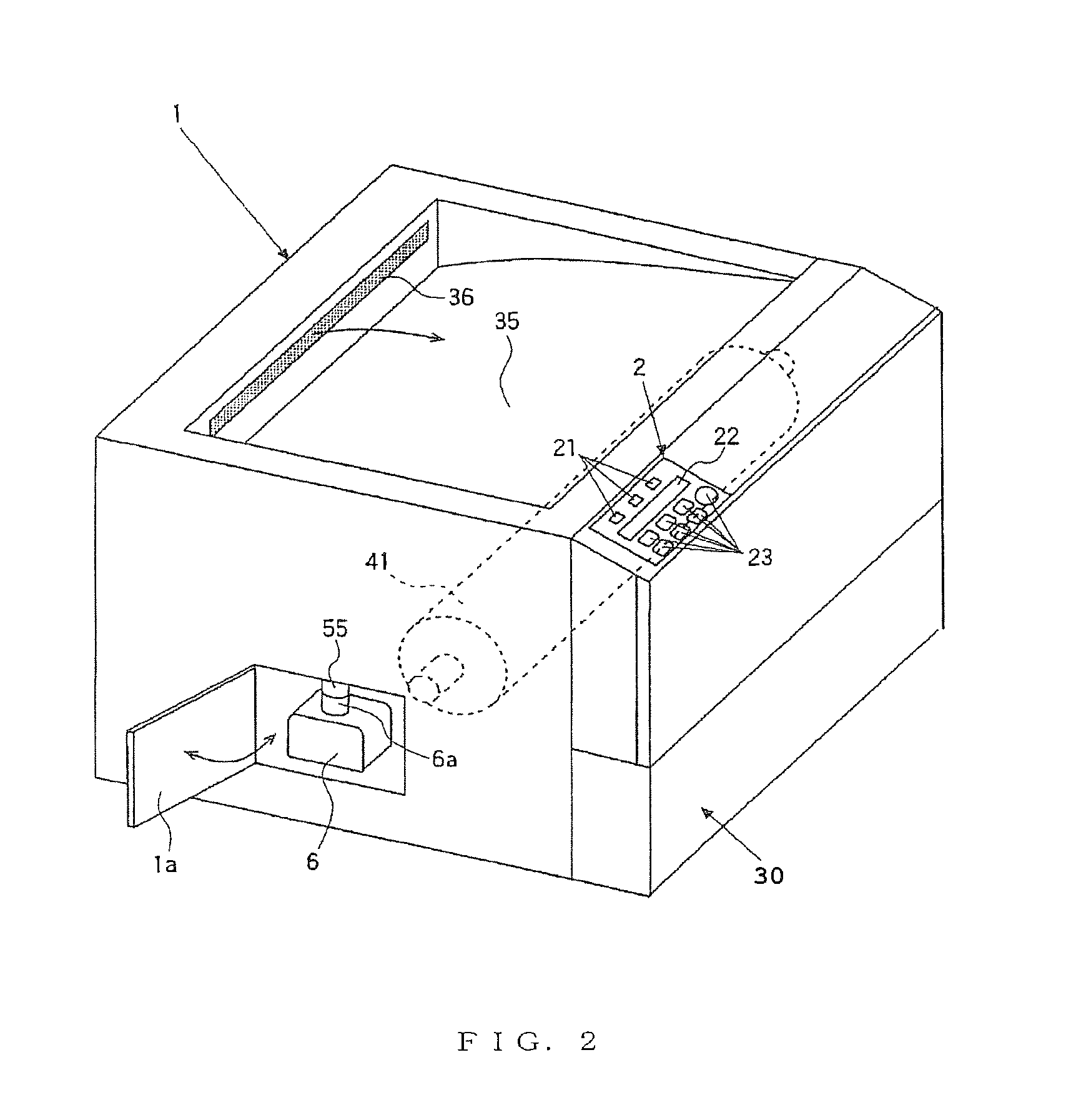
[0035]In the following embodiments of the present invention, reference is made to the drawings. In the drawings, the same members are denoted by the same reference symbols, and redundant descriptions thereof are omitted as appropriate. Further, in the drawings, some members may be irrelevant to the description and are therefore omitted as appropriate.

[0036]Referring to FIGS. 1 to 10B, an embodiment of the present invention will be described. Note that the elements, such as the design and the arrangement, described in this embodiment are merely representative and are not intended to limit the scope of the invention.

[0037]Schematic Configuration of Image Forming Apparatus

[0038]Referring to FIG. 1, a schematic configuration of a printer 1 (e.g., an image forming apparatus) according to an embodiment of the present invention will be described. FIG. 1 is a schematic vertical cross-sectional left side view for explaining the printer 1 according to an embodiment the present invention. In F...


PUM


Abstract

An image forming apparatus includes a waste-toner container, a light sensor having a light-emitting portion and a light-receiving portion, a light-blocking member for covering the light sensor to detect the attachment of the waste-toner container, and a control unit. When the waste-toner container is determined to be full based on the output voltage of the light sensor, a printing operation is stopped or is not started until it is determined that the waste-toner container is removed and then attached, and that the waste-toner container is not full. A method for detecting the fullness of a waste-toner container includes the steps of detecting the fullness of the waste-toner container, prohibiting printing, detecting whether or not the waste-toner container is attached, and permitting printing.

Description

[0001]This application is based upon and claims the benefit of priority from the corresponding Japanese Patent application No. 2008-332849 filed Dec. 26, 2008, the entire contents of which are incorporated herein by reference.BACKGROUND[0002]1. Field of the Invention[0003]The present invention relates to image forming apparatuses, such as copiers, printers, and facsimiles, and methods for detecting the fullness of waste-toner containers.[0004]2. Description of the Related Art[0005]In general, electrophotographic image forming apparatuses, which use toner, perform image formation (printing) by forming a toner image on a photosensitive drum, transferring the toner image to a recording medium such as a sheet, and fixing the image on the sheet. The toner that was not transferred to the recording medium (waste toner) is collected. A waste-toner container for storing the waste toner is provided in the image forming apparatus.[0006]If the waste toner continues to be sent to the waste-toner...

Claims


Application Information

Patent Timeline
Patent Type & Authority Patents(United States)
IPC IPC(8): G03G15/00
CPCG03G21/12G03G15/556G03G2215/0894
Inventor KOBAYASHI, KIMIHIKO
Owner KYOCERA DOCUMENT SOLUTIONS INC
Learn More