Link assembly with defined boundaries for a snake like robot arm

a robot arm and link technology, applied in the field of robot arms, can solve the problems of link movement in an uncontrolled or unpredictable manner, lower stiffness, and lower position accuracy

Active Publication Date: 2012-06-26
OLIVER CRISPIN ROBOTICS
View PDF24 Cites 19 Cited by
  • Summary
  • Abstract
  • Description
  • Claims
  • Application Information

AI Technical Summary

Benefits of technology

[0006]Accordingly, what is desired then is an arm assembly that is stable and can be manipulated precisely.
[0007]It is also desired to provide an arm assembly in which the actual position of individual links may be accurately determined.
[0008]It is further desired to provide an arm assembly that exhibits relatively high stiffness and position accuracy, and avoids exhibiting hysteresis errors.

Problems solved by technology

If the cables are a loose fit within the apertures then, particularly when the arm is straight or passes through the straight position, it is possible that the links will be able to move in an uncontrolled or unpredictable manner.
The device will therefore provide lower stiffness, and lower position accuracy, and may further exhibit hysteresis errors.
However, because of engineering constraints, such as manufacturing tolerances, the need to push the cables through the apertures when the arm is constructed, the tendency of cables to change diameter with changing load, and the need to be able to move the cables within the apertures when the arm is in use, in practice it has been determined that the apertures should be provided slightly larger than the cable diameter.
This, however, inevitably results in a small error in the positioning of the arm, which is difficult to calculate and take account of in controlling the arm shape.

Method used


Image

  • Link assembly with defined boundaries for a snake like robot arm
  • Link assembly with defined boundaries for a snake like robot arm
  • Link assembly with defined boundaries for a snake like robot arm

Examples


Embodiment Construction

[0053]Referring now to the drawings, wherein like reference numerals designate corresponding structure throughout the views.

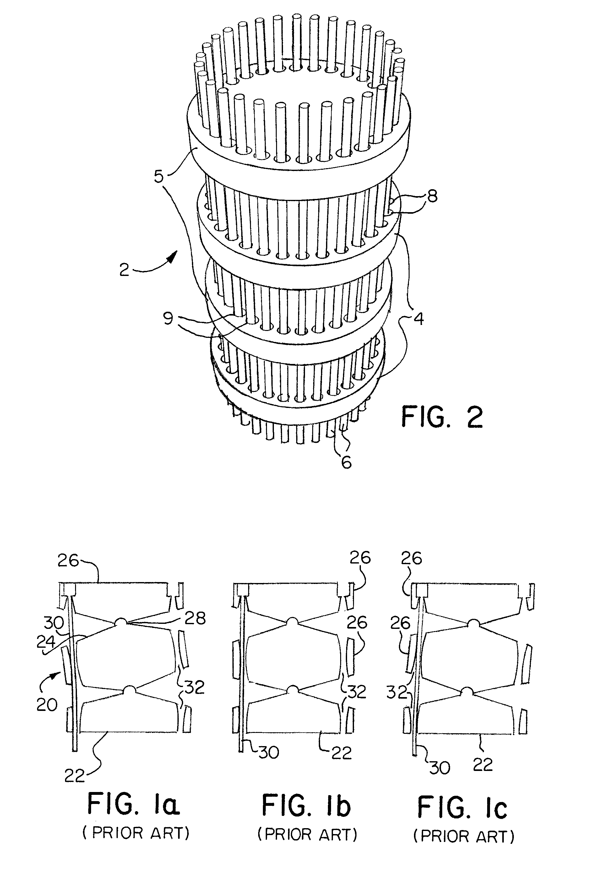
[0054]Referring to FIGS. 1a to 1c, the same section of a robotic arm 20 is shown, which comprises a base link 22, a mid-segment link 24, and a segment tip link 26, having articulated joints 28 therebetween. A control cable 30 is shown extending from the proximal end of the arm through the base link 22 and the mid-segment link 24 and terminating at the segment tip link 26. It can be seen that changing the length of the cable 30 alters the position of the tip link 26 to bend the segment of the arm. One or two further similar cables 30 may also be provided arranged around the circumference of the links, but these have been omitted for simplicity.

[0055]In each of the FIGS. 1a, 1b and 1c, the length of the cable 30 is constant. However, because the cross-sectional size of the apertures is larger that the cross-sectional size of the cable 30, the boundaries or walls ...


PUM


Abstract

In a “tip following” robotic arm, the apertures through which control cables pass are arranged to ensure that the cables are maintained in contact with at least a part of the aperture, leading to a more stable and controllable arrangement.

Description

CROSS-REFERENCE TO RELATED APPLICATIONS[0001]This application is a continuation-in-part of patent application Ser. No. 10 / 736,354 filed Dec. 15, 2003 now U.S. Pat. No. 7,543,518, which is a continuation of International Patent Application No. PCT / GB02 / 02649 filed Jun. 12, 2002, which designates the United States and claims priority of British Application No. 0114406.2 filed Jun. 13, 2001.FIELD OF THE INVENTION[0002]This invention relates to robotic arms of the type used to reach a remote work site via a convoluted path; for example inside an engine or a human body.BACKGROUND OF THE INVENTION[0003]A known type of robotic arm is able to follow a path to a work site with the body of the arm remaining on the path. This is known as “tip following”. That is, the body of the arm follows the path taken by the tip, in a snake like manner. This may include, for example, an apparatus comprising a support arm for a work head that is to be positioned at a location. This may further include opera...

Claims


Application Information

Patent Timeline
Patent Type & Authority Patents(United States)
IPC IPC(8): B25J17/00
CPCB25J9/06B25J9/104B25J18/06Y10T74/20323Y10T74/20329
Inventor BUCKINGHAM, ROBERT OLIVERGRAHAM, ANDREW CRISPIN
Owner OLIVER CRISPIN ROBOTICS
Why Eureka
Try Eureka