
Seismic source arrays

a source array and seismic technology, applied in the field of seismic source arrays, can solve the problems of only achieving phase control, reducing the signal-to-noise ratio, and undesirable azimuthal directivity in seismic data

Active Publication Date: 2012-06-26
REFLECTION MARINE NORGE AS
View PDF19 Cites 42 Cited by
  • Summary
  • Abstract
  • Description
  • Claims
  • Application Information

AI Technical Summary

Benefits of technology

[0032]The invention is not limited to the specific embodiments described hereinafter. In particular, the invention recognises that perturbations to the symmetry of the geome

Problems solved by technology

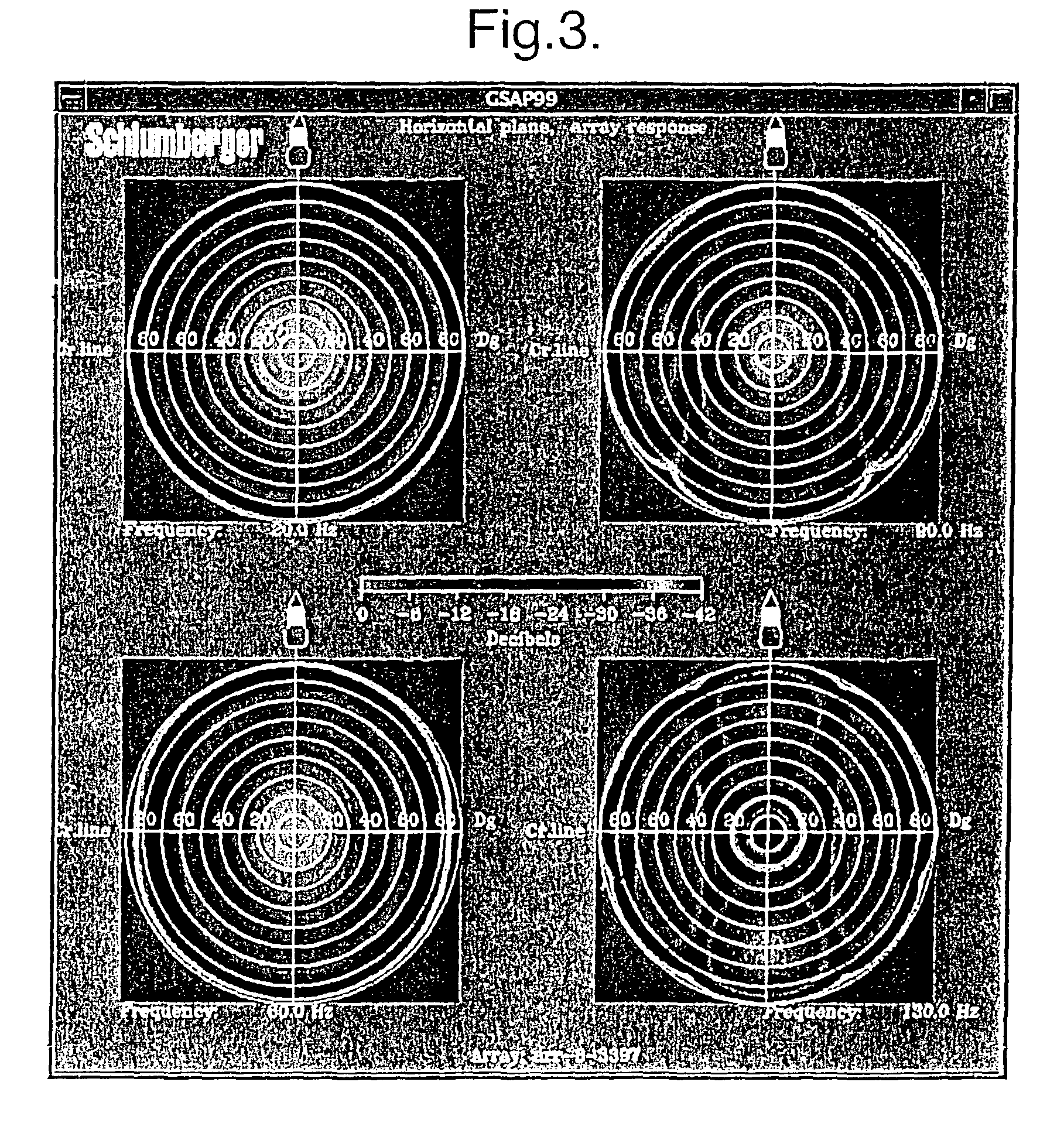
The presence of azimuthal directivity in the seismic data is undesirable.
Azimuthal directivity will have a detrimental effect: it results in a loss of resolution and a reduction of the signal-to-noise ratio.
However, phase control is only achieved within a limited range of take-off angles, and although the beam pattern is identical within the limited range of take-off angles where phase control is achieved, the beam pattern is not identical outside this limit.

Method used


Image

  • Seismic source arrays
  • Seismic source arrays
  • Seismic source arrays

Examples


Embodiment Construction

[0055]FIGS. 1 to 7 have already been described above in relation to the background to the invention.

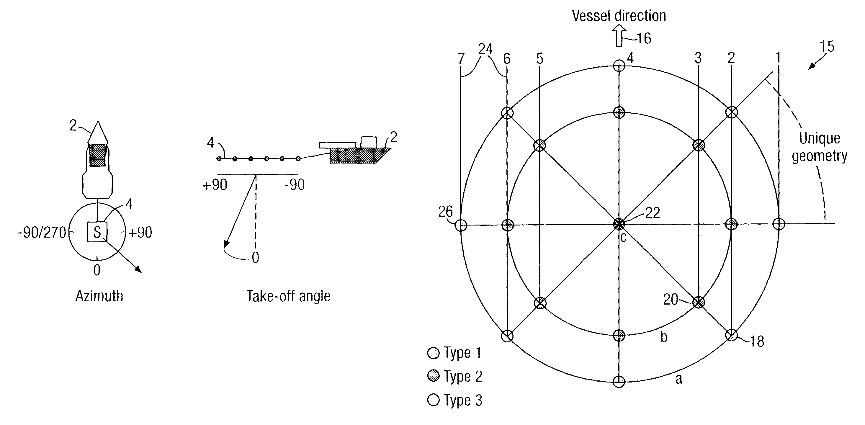
[0056]FIG. 8 shows an example of an azimuth-invariant source geometry for a source array 15. The vessel direction is indicated by arrow 16. Eight sources 18 of type 1 are spaced equally on an outer circle labelled “a”, eight sources 20 of type 2 are spaced equally around an inner circle labelled “b”, and a single source 22 of type 3 is located at the centre of the array 15. The geometry of the array is the result of a design procedure consisting of the following steps:[0057]1. Select the radius of the outer circle. The outer dimension of the array generally determines the width of spatial mainlobe.[0058]2. Select the angular sampling interval, Δθ=360° / N, where N is the number of elements on each circle. E.g. in FIG. 8, Δθ=45°. A dense angular sampling will give small variations with azimuth angle.[0059]3. Distribute equal elements regularly over the circle at the same depth.[0060]4. D...


PUM


Abstract

A seismic source array 15 comprises a plurality of seismic source 26 arranged about a central point of the source array 15 in such a way that an imaginary circle drawn with said central point at its center, and containing all of said seismic sources 26, can be divided into at least three whole sectors each of which contains a substantially identical arrangement of seismic sources 26.

Description

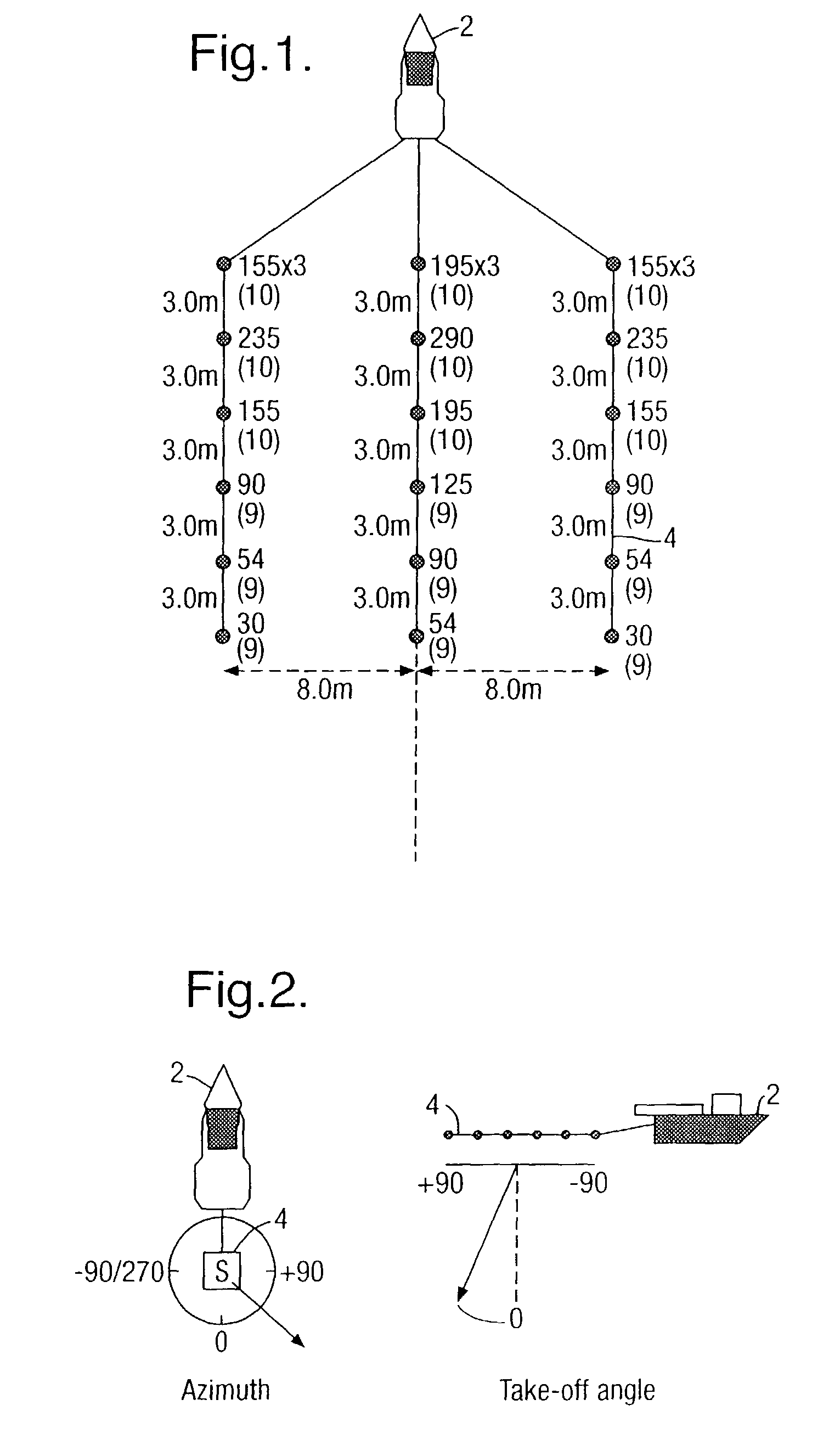
BACKGROUND OF THE INVENTION[0001]1. Field of the Invention[0002]The invention relates to seismic source arrays.[0003]2. Description of the Related Art[0004]Seismic data are usually acquired using arrays of seismic sources. In a source array, individual seismic sources are arranged in a certain spatial pattern. The most common marine seismic sources are airguns but also vibrators, waterguns and steam-injection guns are in use. The most common land seismic sources are vibrators and dynamite charges. Seismic source arrays are usually made up of one type of source. The sizes and strengths of the individual sources within the array may be different. In addition, the individual sources can be made to fire or start emitting at the same time or with small time delays between them.[0005]In marine seismic surveys, the source array is usually towed by a vessel. A typical configuration is shown in FIG. 1, in which a vessel 2 tows an airgun source array 4. In land seismic surveys, a vibrator is ...

Claims


Application Information

Patent Timeline
IPC IPC(8): G01V1/02G01V1/38G01V1/04G01V1/00
CPCG01V1/3861G01V1/006
Inventor HOPPERSTAD, JON-FREDRIKSYNNEVAAG, JOHAN-FREDRIKVERMEER, PIETER LEONARD
Owner REFLECTION MARINE NORGE AS
Learn More