Plug lock structure

a plug lock and locking technology, applied in the direction of lock applications, coupling device connections, transportation and packaging, etc., can solve the problems of power feeding plug itself being stolen, the time required to charge the battery of an electric vehicle is relatively long, and the vehicle is often left unattended

Inactive Publication Date: 2012-06-26
KK TOKAI RIKA DENKI SEISAKUSHO
View PDF39 Cites 55 Cited by
  • Summary
  • Abstract
  • Description
  • Claims
  • Application Information

AI Technical Summary

Benefits of technology

[0005]The present invention provides a plug lock structure that prevents unauthorized removal of a power feeding plug.

Problems solved by technology

The time required to charge the battery of an electric vehicle is relatively long compared to filling a gasoline vehicle with fuel.
Thus, the vehicle is often left unattended over a long period of time with the power feeding plug connected to the inlet of the vehicle.
As a result, someone may remove the power feeding plug from the vehicle when power is being fed and connect the power feeding plug to an inlet of another vehicle to steal electricity.
Further, the power feeding plug itself may be stolen.

Method used


Image

  • Plug lock structure
  • Plug lock structure
  • Plug lock structure

Examples


first embodiment

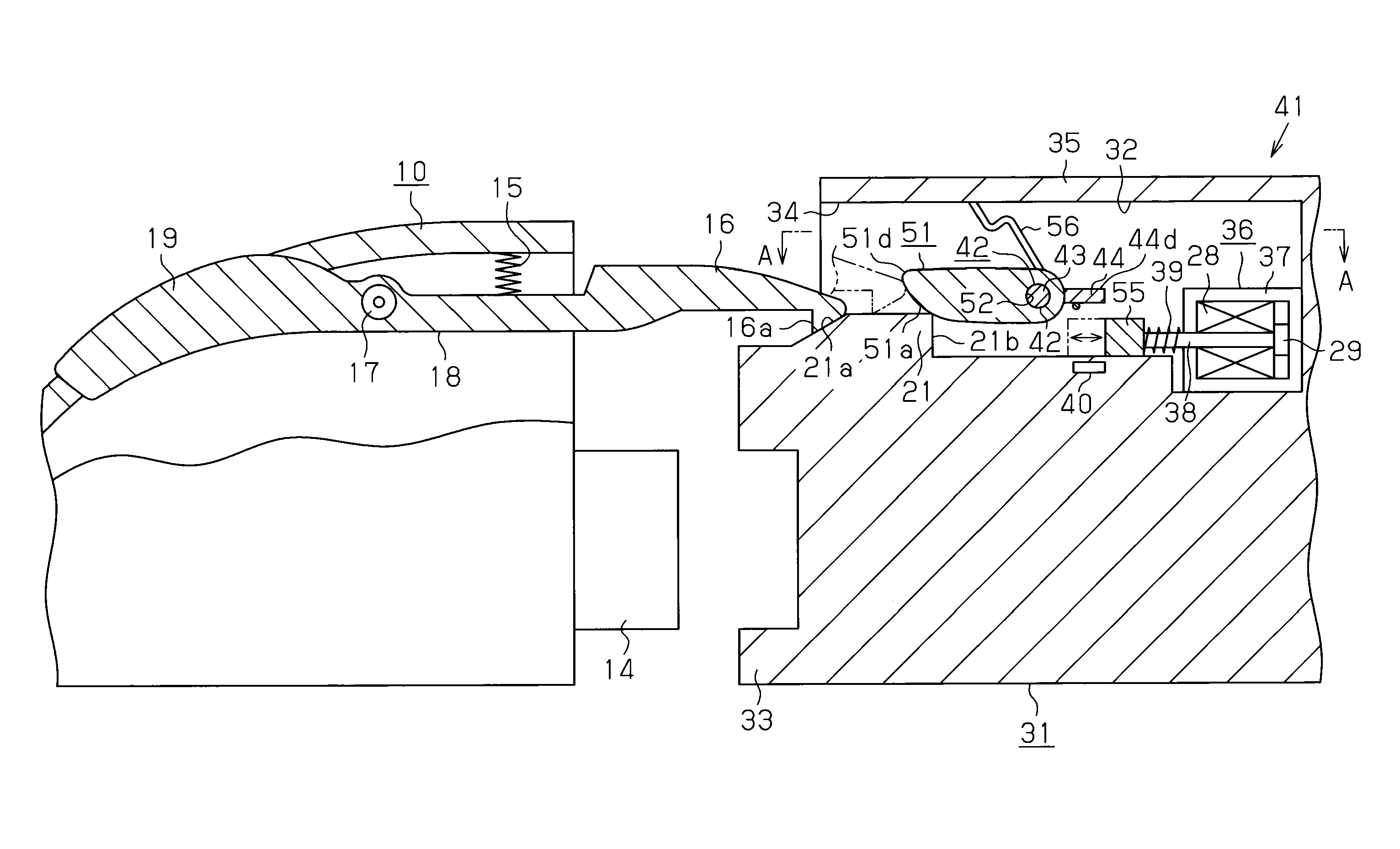
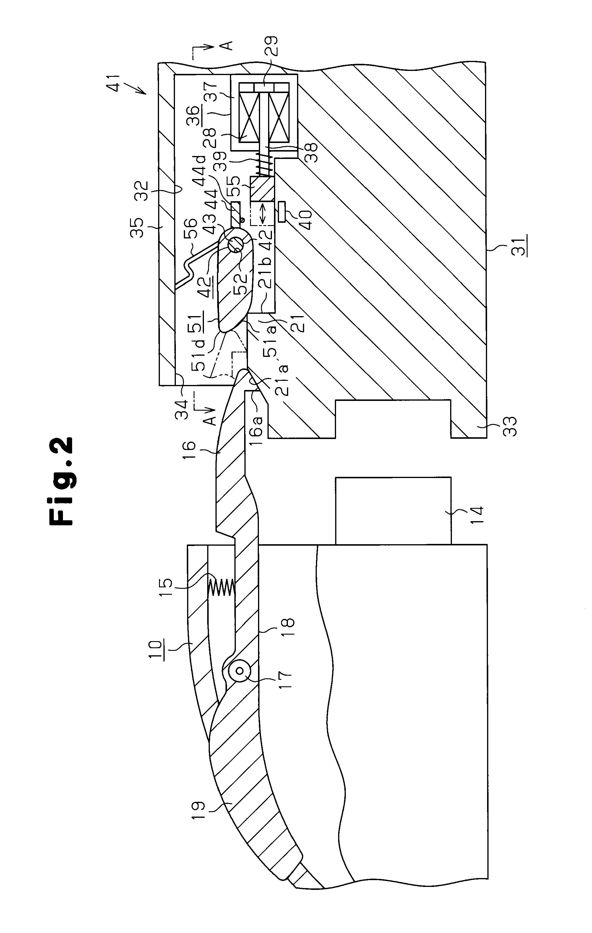
[0019]A first embodiment of a plug lock structure will now be described with reference to FIGS. 1 to 6.

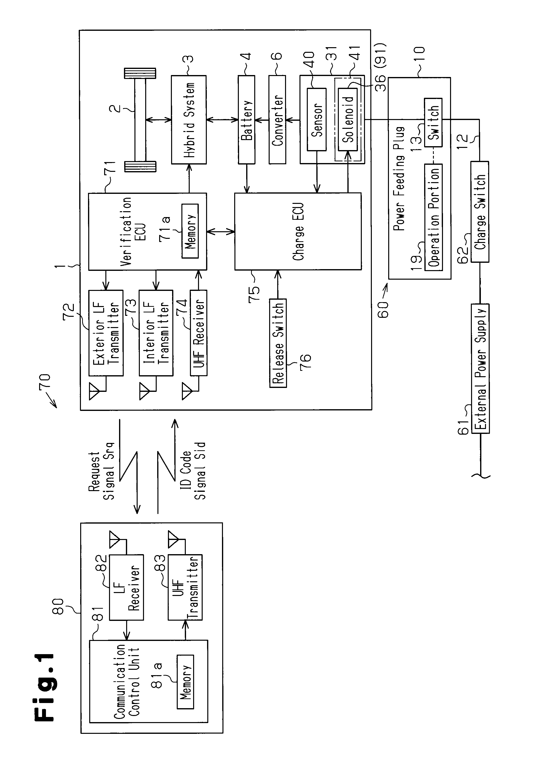
[0020]Referring to FIG. 1, a hybrid vehicle 1 includes a hybrid system 3 that uses an engine and a motor as driving sources that drive wheels 2. The hybrid system 3 operates in various modes, such as a mode for mechanically transmitting power from only the engine to the wheels 2, a mode for generating electric power with the engine to run the motor and drive the wheels 2, a mode for directly driving the wheels 2 with both the engine and the motor, and a mode for driving the wheels 2 with only the motor and without the engine.

[0021]The hybrid system 3 is connected to a battery 4 that supplies the battery 4 with power. In addition to being charged with the electric power generated by the engine, the battery 4 can be charged by an external power supply 61 from outside the vehicle 1.

[0022]The vehicle 1 includes an electronic key system 70 that allows the doors to be locked and unlocked...

second embodiment

[0072]A second embodiment will now be described with reference to FIGS. 7 and 8. In the second embodiment, the lock structure 41 differs from that of the first embodiment. Differences from the first embodiment will now be described in detail.

[0073]In the second embodiment, a motor 91 is used in lieu of the solenoid 36 shown in FIG. 1. Further, as shown in FIG. 8, a lock bar 92 of the second embodiment differs from that of the first embodiment in that it is formed by a stepped plate. The lock bar 92 is pivotally supported in a state inserted into a hooking cavity 94. For example, the lock bar 92 includes a first plate portion 95, a second plate portion 96, and a connecting portion 97. The first plate portion 95 is located in the hooking cavity 94. The second plate portion 96 projects out of the hooking cavity 94. The connecting portion 97 is inclined and connects the first and second plate portions 95 and 96. The first plate portion 95 is parallel to the second plate portion 96. The ...


PUM


Abstract

A plug lock structure that locks a power feeding plug to an inlet, which is fixed to a power feeding subject. The inlet includes a catch. The power feeding plug includes a hook, hooked to the catch, and an operation portion, which separates the hook from the catch. The plug lock structure includes a lock member pivoted in a direction in which the lock member forces the hook against the catch and a direction in which the lock member moves away from the catch together with the hook. A lock block is moved between a first position, at which the lock block permits pivoting of the lock member when the hook moves from the hooked state, and a second position, at which the lock block restricts pivoting of the lock member by contacting the lock member when the hook moves from the hooked state.

Description

CROSS-REFERENCE TO RELATED APPLICATIONS[0001]This application is based upon and claims the benefit of priority from prior Japanese Patent Application No. 2010-195672, filed on Sep. 1, 2010, the entire contents of which are incorporated herein by reference.BACKGROUND OF THE INVENTION[0002]The present invention relates to a plug lock structure.[0003]Automobile manufactures are now concentrating on the development of electric vehicles to lower exhaust gas emissions. An electric vehicle uses a battery as a power source. The battery must be charged, for example, in a household or at a charging station whenever the state of charge of the battery becomes low. Japanese Laid-Open Patent Publication No. 9-161898 describes a charging system that is applied to an electric vehicle. In this charging system, a vehicle includes an inlet, which is connectable to a power feeding plug that extends from, for example, a household outlet of a commercial power supply. When the power feeding plug is connec...

Claims


Application Information

Patent Timeline
Patent Type & Authority Patents(United States)
IPC IPC(8): H01R13/627
CPCB60L11/14B60L11/1818B60L2210/30B60L2270/32B60L2270/34Y02T10/70Y02T90/127Y02T90/14Y02T10/7077Y02T10/7241Y02T10/7005B60L50/16B60L53/16H01R13/6275Y02T10/7072Y02T10/72Y10T70/5009Y02T90/12
Inventor KATAGIRI, TOSHIHARUKAHARA, KEIJI
Owner KK TOKAI RIKA DENKI SEISAKUSHO
Why Eureka
Try Eureka