Boat propulsion engine

a propulsion engine and boat technology, applied in the direction of marine propulsion, propulsive elements, vessel construction, etc., can solve the problems of difficulty in enforcing water tightness in the lower cowling, inability to achieve adequate boat speed, and difficulty in ensuring water tightness in the upper cowling, so as to reduce the upward splashing of water, reduce the downward sinking, and accelerate smooth

Inactive Publication Date: 2012-06-26
HONDA MOTOR CO LTD
View PDF35 Cites 5 Cited by
  • Summary
  • Abstract
  • Description
  • Claims
  • Application Information

AI Technical Summary

Benefits of technology

[0011]The sinking depth of the stern is reduced by the buoyant member when the boat is at a standstill or moving at low speed, and the tilting of the hull is corrected so as to be nearly horizontal. The buoyancy and the more proximal horizontal orientation of the hull (for overcoming a hump or bow waves) resists and reduces further sinking during acceleration when the boat accelerates (first half of the acceleration stage) from a standstill or low speed travel. The lower surface of the buoyant member slopes downward in the rearward direction, thereby providing advantages in that lift is produced by the resistance of the sloped surface, the time required for the boat to overcome bow waves during acceleration can be shortened, and smooth acceleration can be achieved. Therefore, retrofitting and integration with the boat propulsion engine can furthermore be simplified because the buoyant member has buoyancy and lifting function.
[0013]The boat propulsion engine described above preferably further comprises an anti-cavitation plate disposed above the propeller, wherein the sloped surface is disposed above and at a distance from the anti-cavitation plate. Therefore, when rearward sinking is not required in the first half of the acceleration stage, the rear end portion of the lower surface of the buoyant member does not make contact with the water and can therefore avoid becoming a resistance during travel. After acceleration, the buoyant member rises above the waterline, and therefore does not form a resistance in the water during travel, and high speed maneuverability is not compromised.
[0015]First, the depth of the stern is reduced by the buoyant member when the boat is at a stand still or moving at low speed, and the tilting of the hull is corrected so as to be nearly horizontal. The buoyancy and the more proximal horizontal orientation of the hull (orientation for overcoming bow waves) resists and reduces further sinking during acceleration when the boat accelerates (first half of the acceleration stage) from a standstill or low-speed travel, and smooth acceleration can be achieved.
[0016]Also, in the boat propulsion engine, the downward-facing surface that is wider than the anti-cavitation plate of the buoyant member effectively reduces the upward splashing of water, i.e., the upward spewing of water caused by the rotation of the propeller.
[0017]Integral moldings and after-mountings on the boat propulsion engine can furthermore be simplified because the engine also has two functions, i.e., a buoyancy function and an anti-splash function.
[0018]The lower surface of the buoyant member preferably has an extended portion that extends further forward than a front end portion of the case body. The lower surface of the buoyant member therefore extends forward from the drive shaft case, and splashing in the upward direction can be effectively reduced.

Problems solved by technology

Since the hull therefore begins to move in a tilted state, the water resistance is considerable when traveling starts, and adequate boat speed cannot be obtained.
There is a problem in that time is required for the boat to approximate an orientation that is nearly horizontal, and the boat cannot smoothly accelerate.
In the outboard engine of the 5-319386 publication, however, a portion of the lower cowling that forms the engine room is structured to submerge, and it is therefore difficult to endow this structure with water tightness when the lower cowling is assembled.
When water has furthermore flooded the engine room, it is difficult to drain the water, the movement of movable components is compromised by water and salt, and the components tend to corrode.
Therefore, the driving noise of the engine passes through the case and the cowlings, and is released to the periphery as engine noise.
In the outboard motor of the 5-319386 publication, the buoyancy of the hull itself only prevents the stern from sinking when the boat accelerates from a standstill in particular, and the design does not provide for actively lifting the stern and quickly bringing the hull into a horizontal state.

Method used


Image

  • Boat propulsion engine
  • Boat propulsion engine
  • Boat propulsion engine

Examples


Embodiment Construction

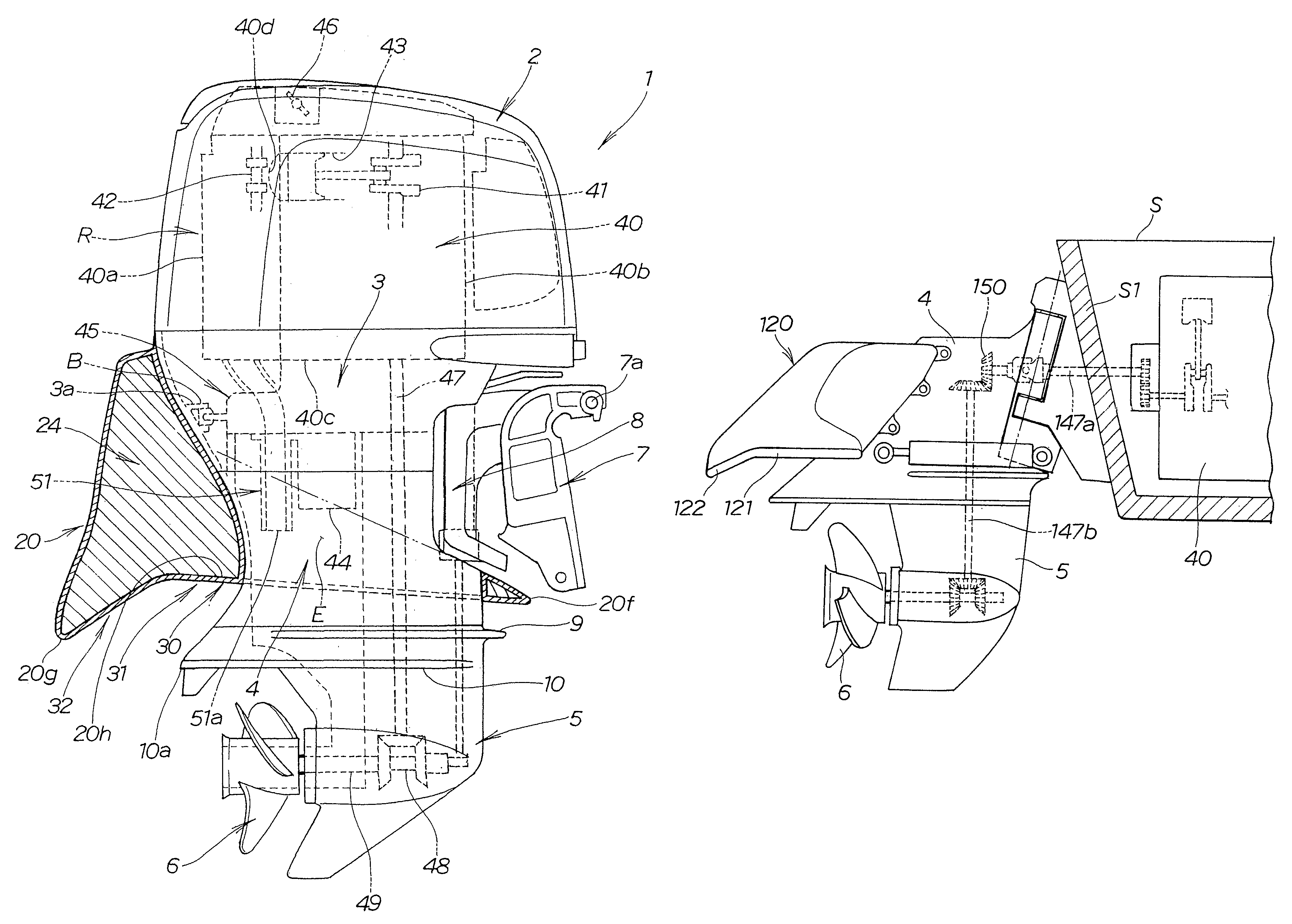
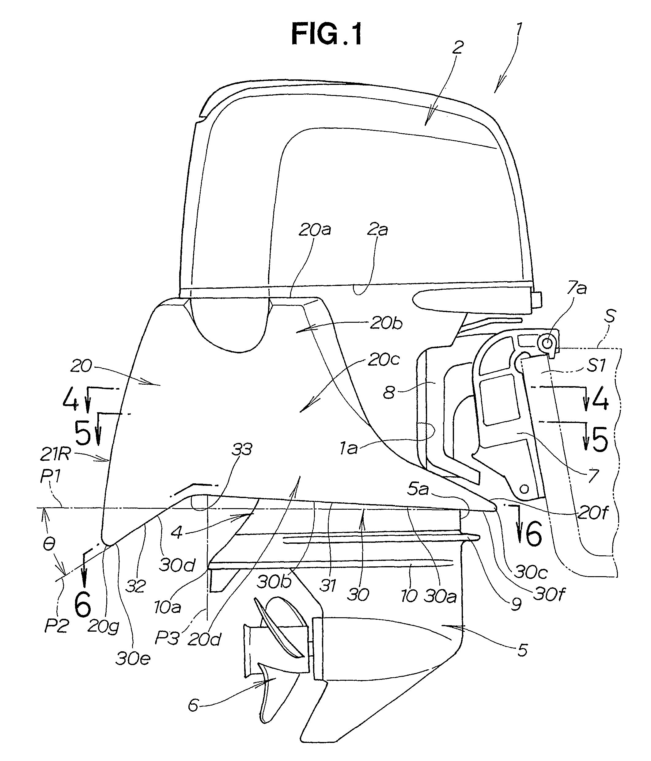
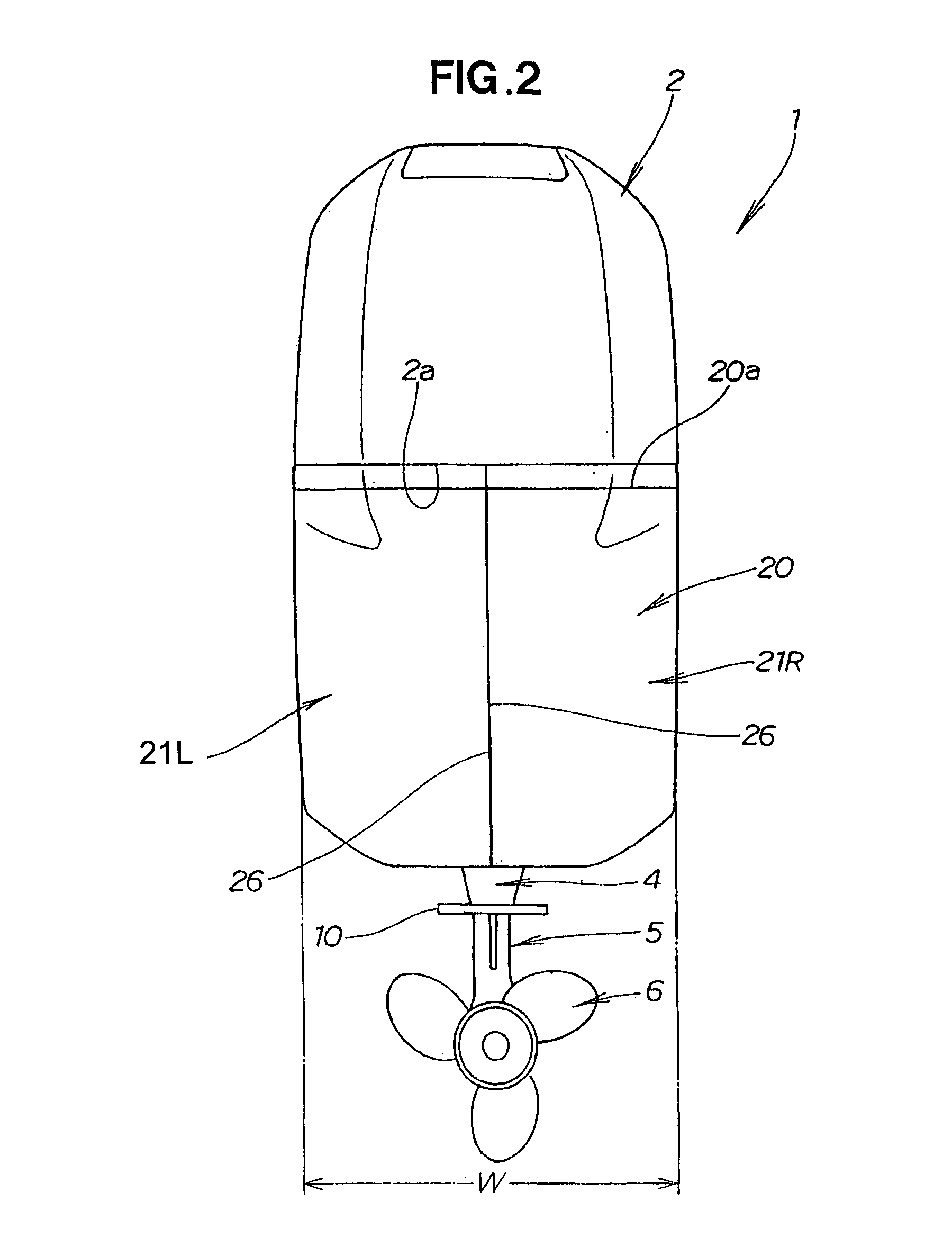
[0030]Referring now to FIGS. 1 to 6 inclusive, description will be made as to a boat propulsion engine or an inboard-engine outboard-drive unit, according to a first embodiment of the present invention. The boat propulsion engine in this embodiment is referred to simply as an outboard motor.

[0031]The outboard engine 1 has a engine cover (top cover) 2 that covers the upper half of an engine (power source) 40, and an undercover 3 that covers the lower half of the engine 40, as shown in FIGS. 1, 2, and 3. An engine room R is formed by the engine cover 2 and undercover 3. An extension case (leg body) 4, which is a drive shaft case, is disposed below the under-cover 3. A gear case 5 having a propeller 6 for propulsion is disposed below the extension case 4.

[0032]A concavity 1a that is concave in the rearward direction of the outboard engine 1 is formed on the front portion of the extension case 4. The outboard engine 1 is mounted on the stern S1 of the hull S by way of a stern bracket 7....


PUM


Abstract

A boat propulsion engine includes a buoyant member (20) disposed on a case body that houses a drive shaft (47) in order to lift the stern. The buoyant member has a lower surface (32) that slopes downward in the rearward direction.

Description

TECHNICAL FIELD[0001]The present invention relates to a boat propulsion engine, often called an inboard-engine outboard-drive unit. More particularly, it relates to such a boat propulsion engine having a buoyant member so as to lift a stern of the boat upward to allow the boat to start moving smoothly from its standstill position.BACKGROUND ART[0002]In a boat that moves by use of a boat propulsion engine which comprises an outboard motor, the level of the stern drops and sinks into the water, and the bow rises and is tilted upward when, for example, the boat is at a standstill and when the boat begins to move. Since the hull therefore begins to move in a tilted state, the water resistance is considerable when traveling starts, and adequate boat speed cannot be obtained. The stern must rise upward a certain amount, and the orientation of the boat must become approximately horizontal in order to reach a certain level of speed. There is a problem in that time is required for the boat t...

Claims


Application Information

Patent Timeline
Patent Type & Authority Patents(United States)
IPC IPC(8): B63H20/00B63H20/32B63H20/34B63B1/24B63B1/16
CPCB63B39/061B63H20/32B63H20/34
Inventor SHIOMI, KAZUYUKIIKENO, TETSUROOKADA, TAKESHI
Owner HONDA MOTOR CO LTD
Why Eureka
Try Eureka