
Medical inspection device

a medical inspection and inspection device technology, applied in the field of medical inspection devices, can solve the problems of deteriorating the correctness of anamneses, forming another inconvenience, and not being able to observe in an ideal way, so as to improve the clearness of the taken image, reduce manufacturing costs, and facilitate repair and maintenance.

Inactive Publication Date: 2012-06-26
APPLE BIOMEDICAL
View PDF4 Cites 9 Cited by
  • Summary
  • Abstract
  • Description
  • Claims
  • Application Information

AI Technical Summary

Benefits of technology

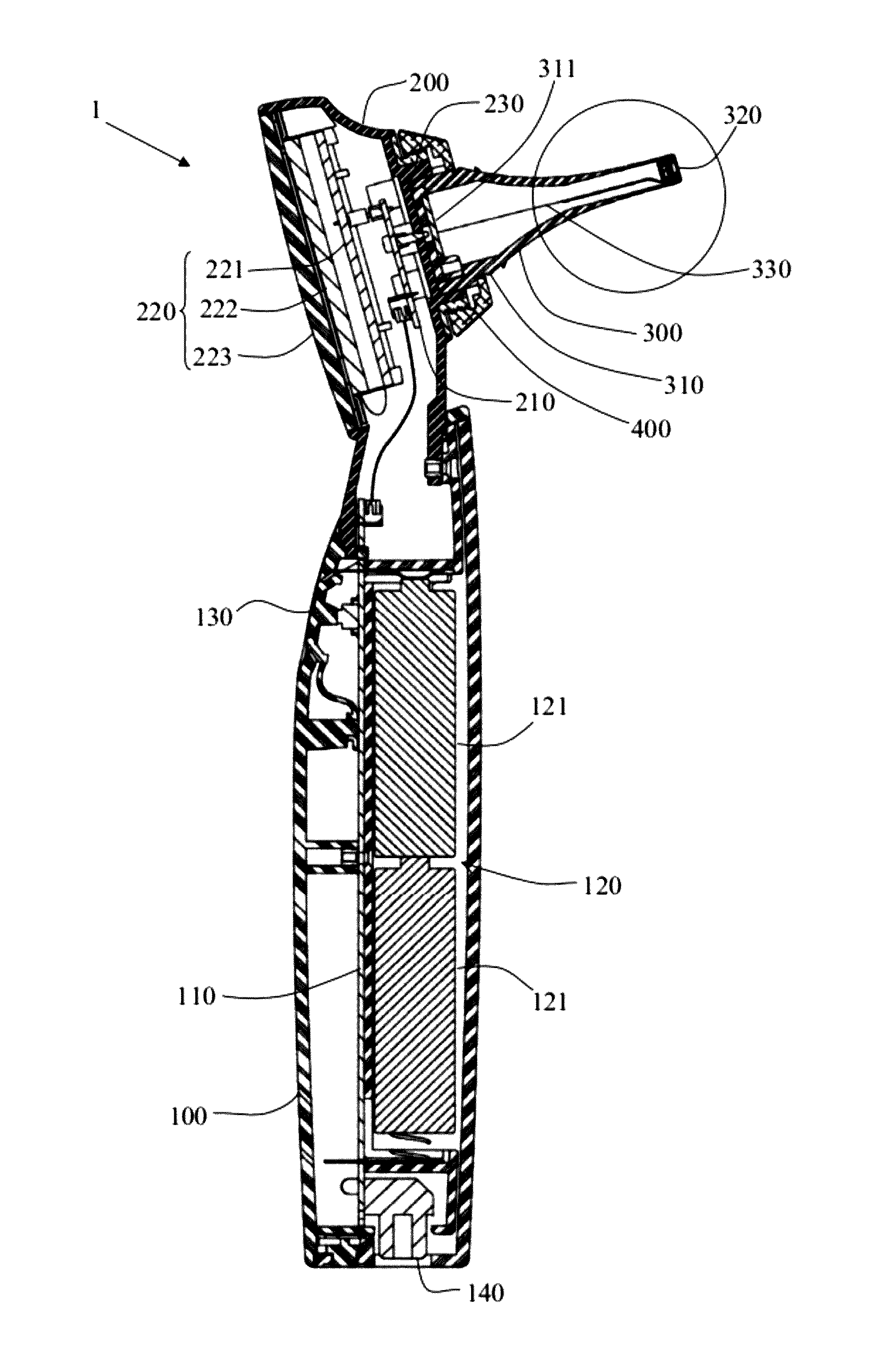
"The present invention is an improved medical inspection device with several technical effects. Firstly, the inspection portion is detachably assembled with the body, making it easier to repair and maintain. Secondly, the device has a light source arranged at the end of its speculum portion, saving the use of additional light pipes and reducing manufacturing costs. Thirdly, the device has a handheld portion and a display portion with a printed circuit board and an image display module, allowing users to hold and operate the device. The inspection module has an inspection portion with a lens, image sensing unit, and light source for improving image quality. The device also has a fastening ring for secure attachment to the display portion. Overall, the present invention provides a more convenient, cost-effective, and efficient medical inspection device."

Problems solved by technology

This can probably bring eyestrain to the user, and thus is not an ideal way to make observation.
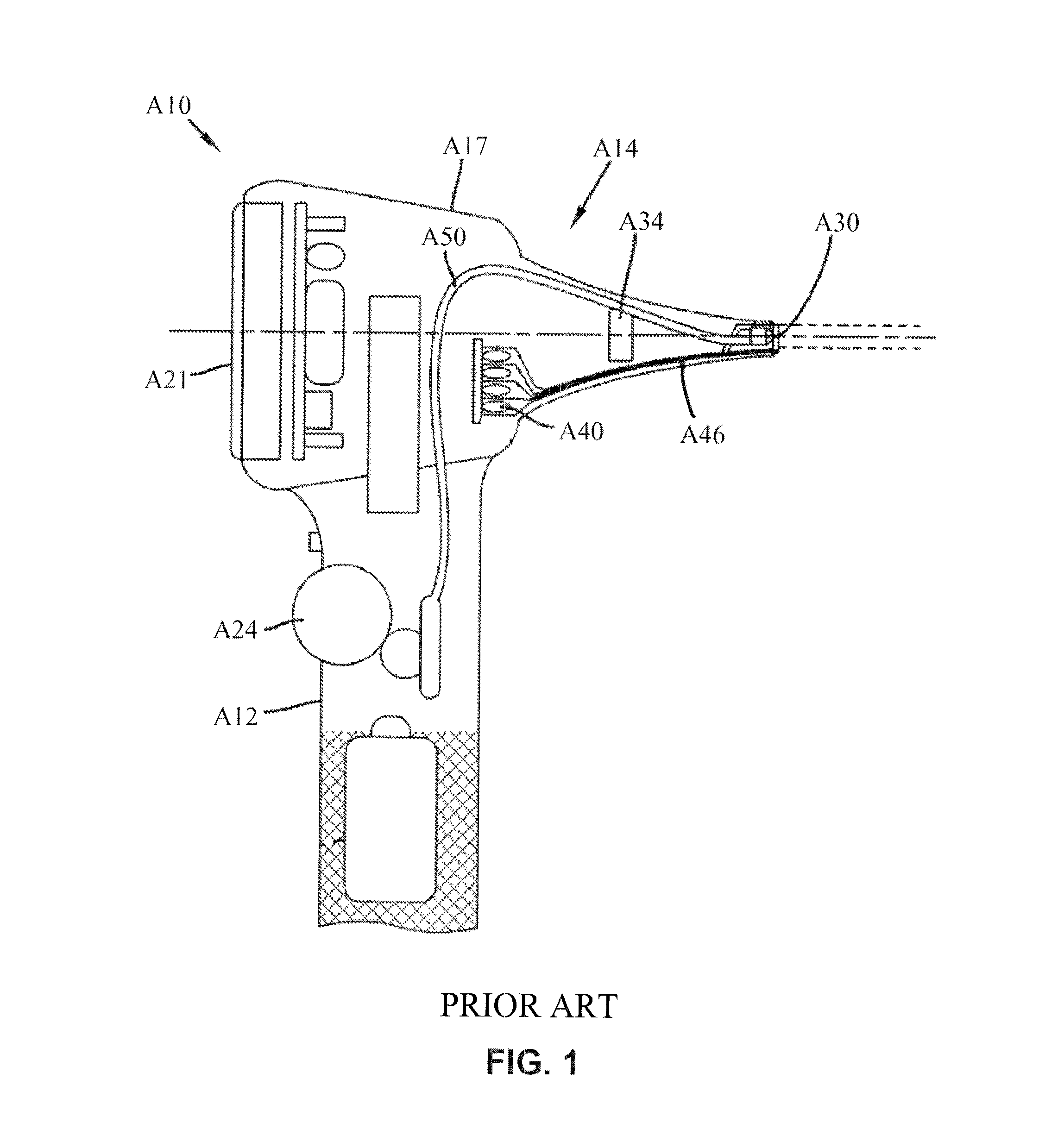
Besides, in use of the conventional hand-held examining device, additional light sources are usually required to illuminate the dark interior of organs for clear observation, thus forming another inconvenience.
Consequently, the correctness of anamneses can be deteriorated if there is any inaccuracy existing in such sketches.
However, since the medical inspection device A10 is integratedly formed, it is impossible to detach the speculum portion A14 for separate disinfection, thus being very inconvenient.
Besides, the light pipe A46 itself increases the overall manufacturing cost.

Method used


Image

  • Medical inspection device
  • Medical inspection device
  • Medical inspection device

Examples


Embodiment Construction

[0025]To achieve the foregoing objectives and effects, the inventor of the present invention makes improvement to the conventional medical inspection device, by configuring the inspection portion as detachable, and rearranging the internal components, so as to excogitate an improved medical inspection device of the present invention. Hereinafter, a first preferred embodiment and a second preferred embodiment of the medical inspection device of the present invention will be described in detail so as to illustrate the structural and technical features of the present invention.

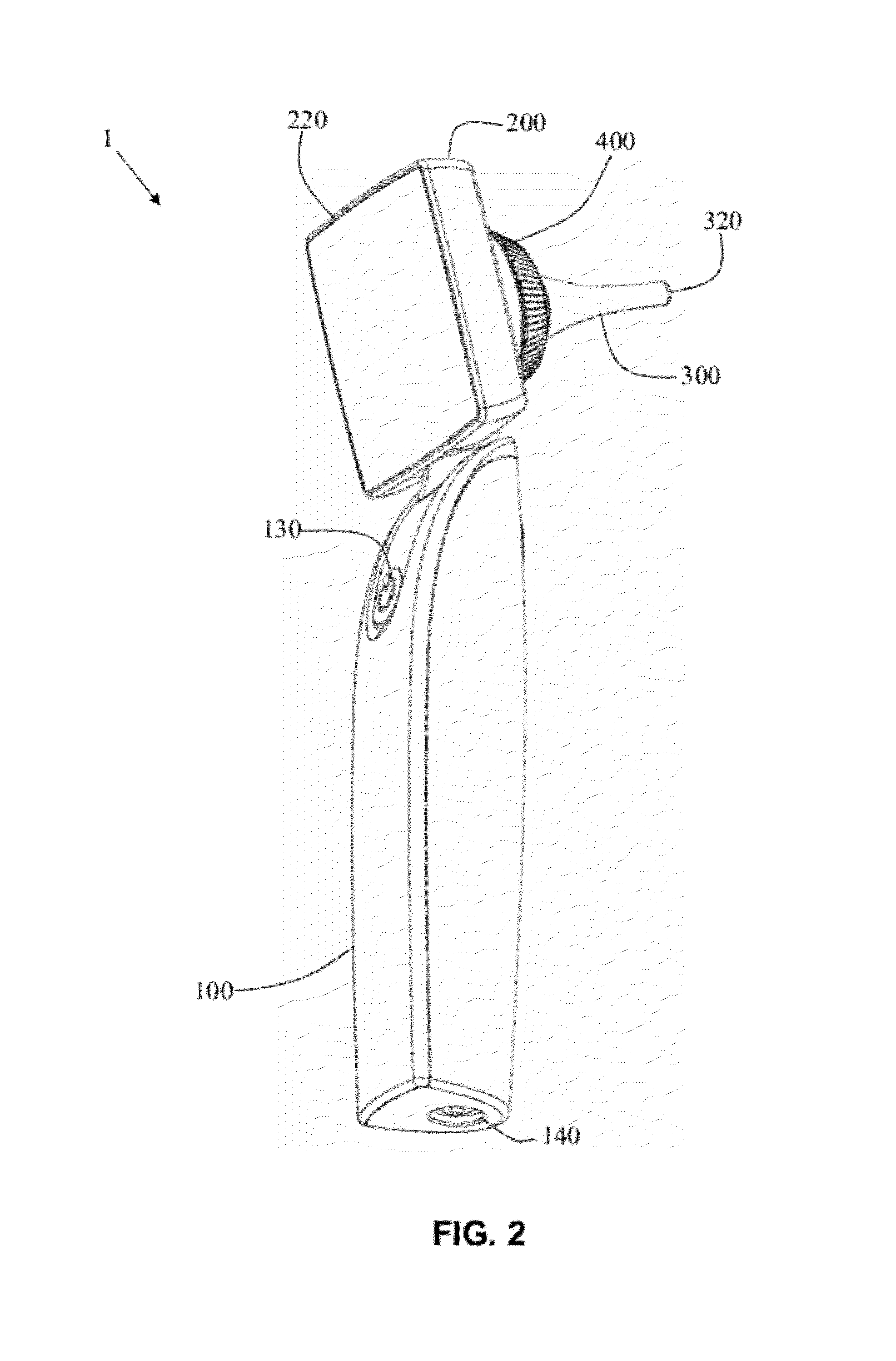
[0026]Firstly, please refer to FIG. 2, FIG. 3, FIG. 4, FIG. 5 and FIG. 6 simultaneously. FIG. 2 is a perspective view of a medical inspection device according to a first preferred embodiment of the present invention. FIG. 3 is a partially exploded view of the medical inspection device according to the first preferred embodiment of the present invention. FIG. 4 is a partially exploded view of the medical inspectio...


PUM


Abstract

An improved medical inspection device at least comprises a hand-held portion, a display portion being connected with the hand-held portion and comprising a first printing circuit board, an image display module, an annular protuberance and at least one electrode contact, an inspection module comprising a joint portion, an inspection portion and a third printing circuit board, wherein the joint portion has a second printing circuit board provided at an inner surface thereof, and the inspection portion further comprises a lens, an image sensing unit and a light source, and a fastening ring that is detachably fastened with the annular protuberance of the display portion so as to firmly fasten the joint portion of the inspection module to the display portion.

Description

BACKGROUND OF THE INVENTION[0001]1. Technical Field[0002]The present invention related to a medical inspection device, and more particularly, to an improved medical inspection device including a hand-held portion, a display portion, and an inspection module.[0003]2. Description of Related Art[0004]It is common that doctors use conventional hand-held examining devices for otologic, peroral or nasal endoscopy to facilitate diagnosing their patients. Such a conventional hand-held examining device is configured like a magnifying glass, having a grip shank and an observing part. The observing part has its front end formed in a taper for easily entering an organ to be examined. At the distal portion of the tapered part, there is a lens for magnifying an image inside the interior of the organ to be examined so as to facilitate a doctor's diagnosis.[0005]However, in use of the conventional hand-held examining device, to observe the magnified image, the user (i.e. the doctor) has to approach...

Claims


Application Information

Patent Timeline
Patent Type & Authority Patents(United States)
IPC IPC(8): A61B1/227A61B1/06
CPCA61B1/00052A61B1/227
Inventor HUANG, TZAI-KUN
Owner APPLE BIOMEDICAL
Learn More