Fluoride ion cleaning method

a technology of fluoride ions and cleaning methods, applied in the direction of iron halides, lighting and heating apparatus, separation processes, etc., can solve the problems of reduced effectiveness of current fic techniques, and high equipment and maintenance costs

Inactive Publication Date: 2012-06-26
GENERAL ELECTRIC CO
View PDF13 Cites 16 Cited by
  • Summary
  • Abstract
  • Description
  • Claims
  • Application Information

AI Technical Summary

Problems solved by technology

Current FIC techniques either suffer from reduced effectiveness due to the limited availability of HF gas in the process or are burdened by high equipment and maintenance costs stemming from the use of bottled HF gas as a reactant.
Because HF is an extreme toxin, its use requires expensive, relatively complicated equipment in order to safely handle the HF.

Method used


Image

  • Fluoride ion cleaning method
  • Fluoride ion cleaning method
  • Fluoride ion cleaning method

Examples


Embodiment Construction

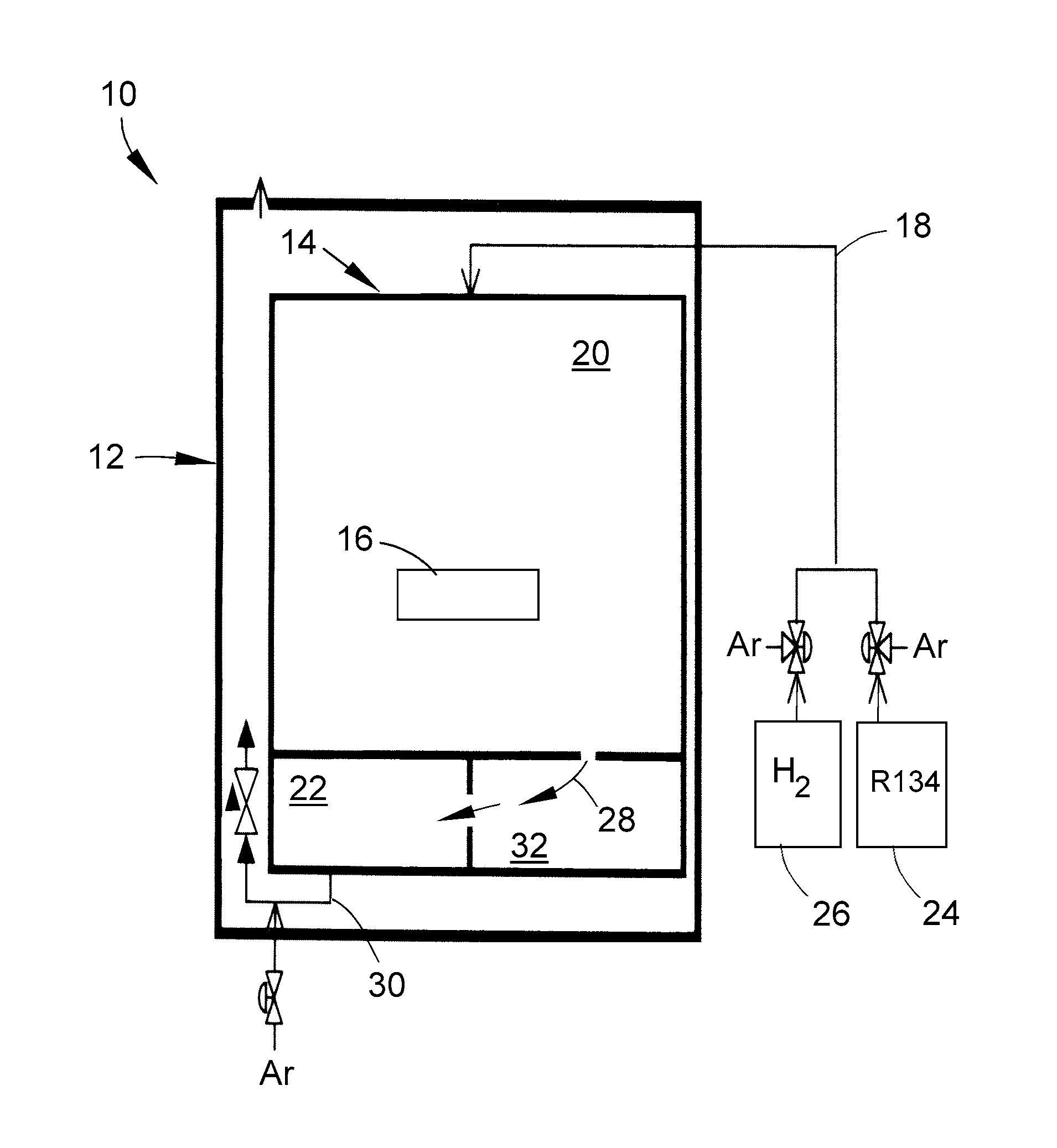
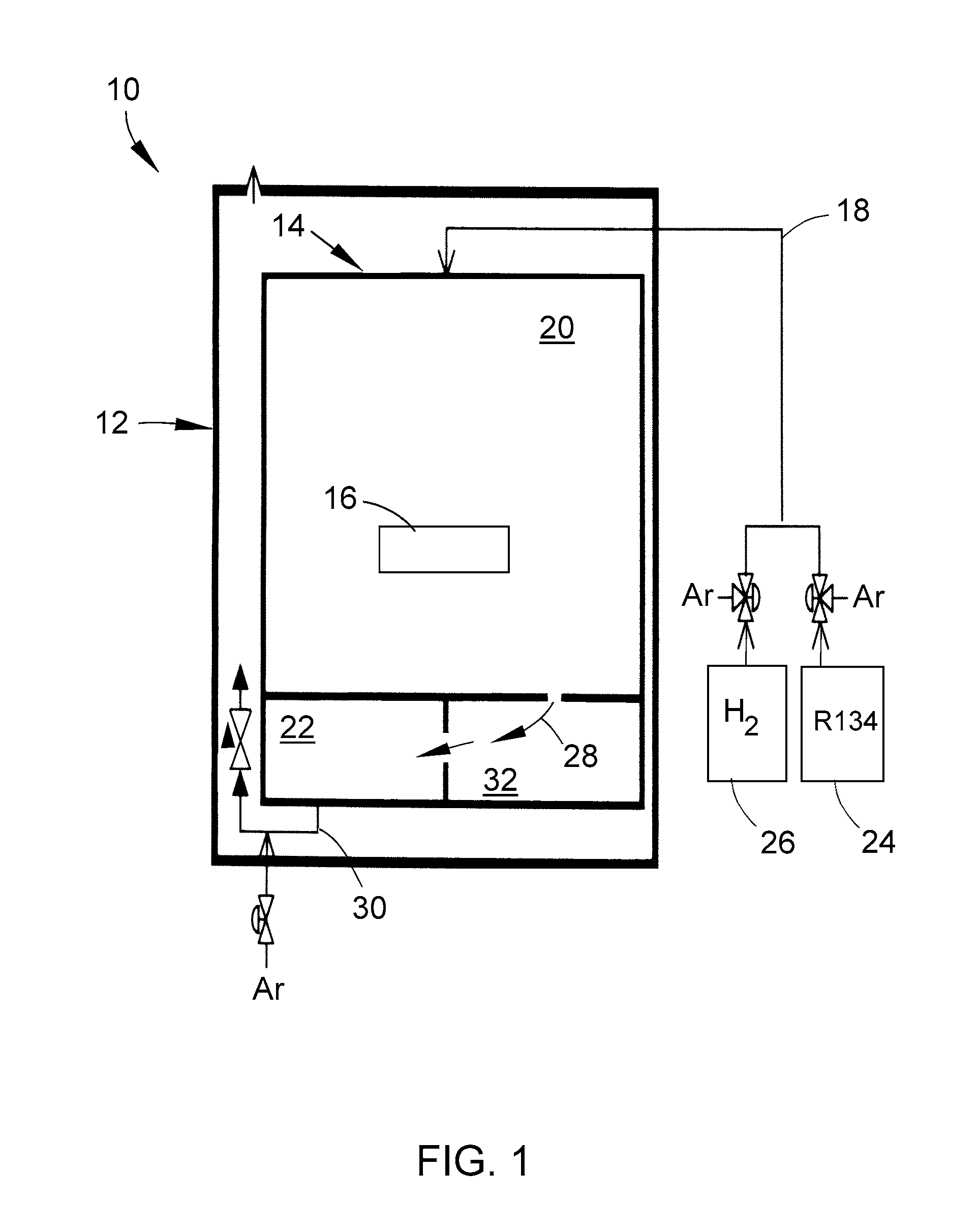
[0011]Referring to the drawings wherein identical reference numerals denote the same elements throughout the various views, FIG. 1 shows an exemplary system 10 including a high temperature furnace 12 including a cleaning retort 14 into which parts or components 16 in need of cleaning are placed. Cleaning retort 14 is capable of containing the appropriate cleaning gasses introduced by gas stream 18. The cleaning retort 14 includes at least two regions. A first region 20 is sized and dimensioned to hold parts and components 16 in need of cleaning. A second region 22 is operable as an HF scrubbing unit (fluorine getter). In an exemplary process, the retort 14 is preheated and purged with, for example, argon. Thereafter, a feedstock of a non-hazardous fluorine-containing compound 24 and hydrogen gas 26 are introduced into the retort 12. The fluorine-containing compound reacts at temperature with hydrogen to form HF gas (gas stream 18) in the retort 14.

[0012]The HF gas then acts to clean...


PUM

PropertyMeasurementUnit
temperaturesaaaaaaaaaa
volatileaaaaaaaaaa
melting temperatureaaaaaaaaaa

Abstract

A fluoride ion cleaning method includes generating hydrogen fluoride (HF) gas in-situ in a cleaning retort; contacting a part in need of cleaning with the generated HF gas; scrubbing an initial effluent stream in-situ to substantially remove residual HF gas therefrom; and passing the scrubbed effluent gas stream out of the cleaning retort. In an exemplary method, a liquid or gaseous halogenated feedstock is introduced into a cleaning retort; hydrogen gas is introduced into the cleaning retort, HF gas is generated by a reaction of the feedstock with hydrogen gas at a sufficient temperature. In an exemplary method, only HF gas generated in-situ or reconstituted in-situ is utilized in the cleaning process.

Description

BACKGROUND OF THE INVENTION[0001]This invention relates generally to systems, methods, and apparatuses for fluoride ion cleaning, and more specifically to in situ generation and capture of hydrogen fluoride gas used to clean components, including components comprising superalloy material.[0002]Fluoride Ion Cleaning (FIC) is used to remove oxides from field-run hot gas path components in preparation for subsequent braze repair operations. Current FIC techniques either suffer from reduced effectiveness due to the limited availability of HF gas in the process or are burdened by high equipment and maintenance costs stemming from the use of bottled HF gas as a reactant.[0003]Commercially available dynamic FIC equipment currently uses bottled HF gas as the source material. Because HF is an extreme toxin, its use requires expensive, relatively complicated equipment in order to safely handle the HF. In addition, since HF must be used in excess in the cleaning process, the effluent stream al...

Claims


Application Information

Patent Timeline
Patent Type & Authority Patents(United States)
IPC IPC(8): B01D53/04B01D53/34B08B5/00
CPCB01D53/685C23G5/00B01D2257/2047B01D2251/404
Inventor MANTKOWSKI, THOMAS E.
Owner GENERAL ELECTRIC CO
Why Eureka
Try Eureka