
Aluminum electrolytic cells having heterotypic structured cathode carbon blocks

a heterotypic structure and electrolysis cell technology, applied in the field of aluminum electrolysis, can solve the problems of reducing the current efficiency, affecting the electrolysis cell, and increasing the power consumption of the direct current production of aluminum electrolysis, so as to reduce the molten aluminum loss, reduce the velocity of the flow and fluctuation of the level of cathodal molten aluminum, and increase the stability of the surface of molten aluminum.

Inactive Publication Date: 2012-06-26
NORTHEASTERN UNIV ENG & RES INST +2
View PDF9 Cites 9 Cited by
  • Summary
  • Abstract
  • Description
  • Claims
  • Application Information

AI Technical Summary

Benefits of technology

[0023]The aluminum electrolytic cell having profiled cathode carbon blocks according to the present invention can reduce the velocity of the flow and fluctuation of the level of cathodal molten aluminum within the electrolytic cell, so as to increase the stability of the surface of molten aluminum, reduce the molten lose of the aluminum, increase the current efficiency, reduce the inter electrode distance, and reduce the energy consumption of the production of aluminum by electrolysis. Further, the compounds or precipitates of viscous cryolite molten alumina can be formed on the lower portion between walls protruding on the upper surface of the cathode, which can prohibit the molten aluminum from flowing into the cell bottom through the cracks and apertures on the cathodes, so that the life of the electrolytic cell can be extended.

Problems solved by technology

More specifically, the inter electrode distance with too low value may increase a secondary reaction between the metal aluminum molten from the cathode surface into the electrolytic melt and the anode gas, so that the current efficiency is reduced.
The inter electrode distance with too high value may increase the cell voltage within the electrolytic cell, so that the power consumption for the direct current of the production of the aluminum electrolyzing is increased.
However, according to the information obtained from the Sixth International Aluminum Electrolyzing Technique Conference in Australia, such experiment only tests for 70 days.
Up to now, there is no solution to solve above problem, so the development and research of such aerial drainage type TiB2 / C cathode the electrolytic cell is impeded.
An other serious disadvantage of the aerial drainage type TiB2 / C cathode electrolytic cell is: there is not enough amount of molten aluminum in the cathode, so that the heat stability of the electrolytic cell is poor, particularly, the huge amount of heat momentarily produced in the electrolytic cell under the anode effect is unable to dissipated through the molten aluminum having good heat conductivity or stored by the molten aluminum.
Moreover, the existing aluminum electrolytic cell is not good in life span; the longest life span for the cathode only has 2500-3000 days.
In those disrepaired electrolytic cells, most of them are damaged in the early period, that is, it is caused by, in the early period of the production within the electrolytic cell, the cathode molten aluminum within the cell is leaked to the cell bottom to melt and corrode the cathode steel rod through cracks formed at the bonding portion between the cathode carbon blocks internally lined in the cell bottom and the carbon pastes during burning and producing, or through the crack produced on the carbon blocks body during burning.

Method used


Image

  • Aluminum electrolytic cells having heterotypic structured cathode carbon blocks
  • Aluminum electrolytic cells having heterotypic structured cathode carbon blocks
  • Aluminum electrolytic cells having heterotypic structured cathode carbon blocks

Examples


Embodiment Construction

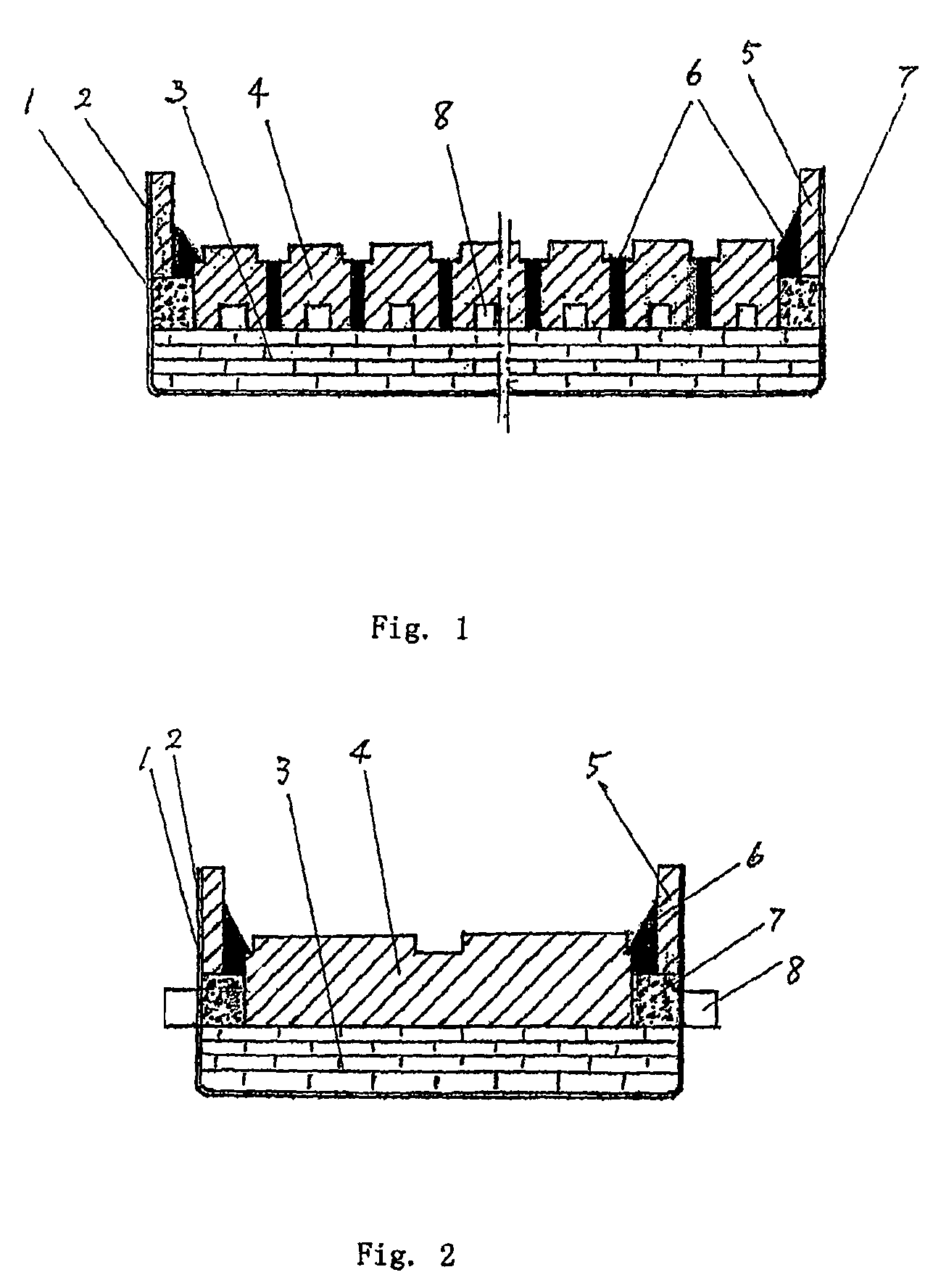
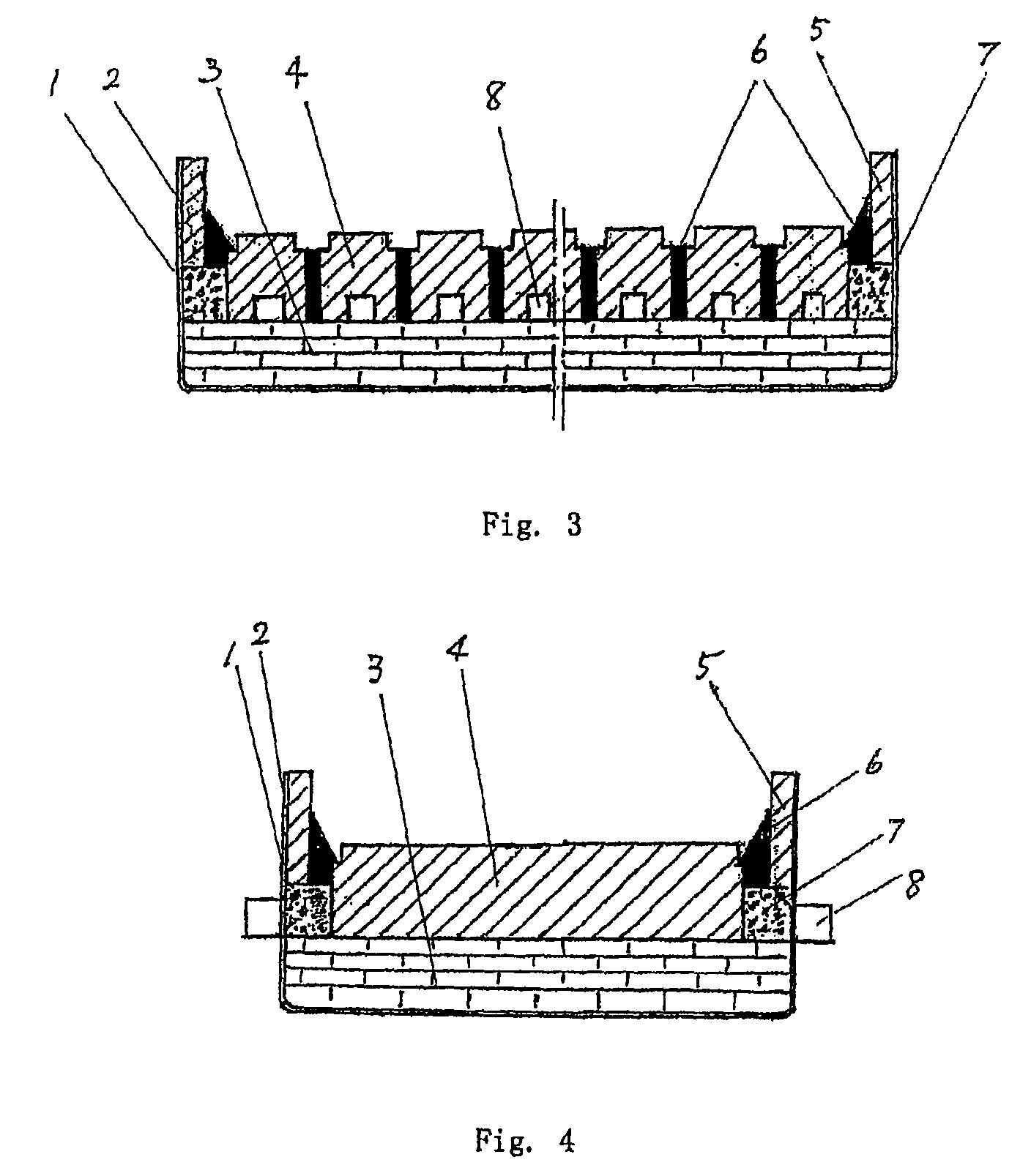
[0045]As shown in FIG. 1, an aluminum electrolytic cell having profiled cathode carbon blocks structures has a coverless rectangular case structure. The outside thereof comprises a steel cell case 1, and the steel cell case 1 is lined with an asbestos board 2. Refractory materials and heat insulating materials 3 are provided on the asbestos board 2 lining within the cell case 1, and cathode carbon blocks at cell bottom 4, each of which the upper surface includes protruding portions, are provided on the refractory materials and the heat insulating materials 3, wherein the profiled cathode carbon blocks 4 with the upper surface thereof having protruding portions are made from anthracites or artificial graphite crumbs or the compound thereof Alternatively, such cathode carbon blocks 4 with the upper surface thereof having protruding portions can be made of graphitized or semi-graphitized carbon blocks. The protruding portions of the profiled cathode carbon blocks 4 each has a width les...


PUM

PropertyMeasurementUnit
heightaaaaaaaaaa
temperatureaaaaaaaaaa
distanceaaaaaaaaaa

Abstract

Disclosed is an aluminum electrolytic cell having profiled cathode carbon blocks structures, comprising a cell case, a refractory material installed on the bottom, an anodes and a cathode. The cathode carbon blocks include a profiled structure having projections on the top surface of the carbon blocks, that is, a plurality of projections are formed on a surface of the cathode carbon blocks. The aluminum electrolytic cell having the cathode structure according to the present invention can reduce the velocity of the flow and the fluctuation of the level of the cathodal molten aluminum within the electrolytic cell, so as to increase the stability of the surface of molten aluminum, reduce the molten lose of the aluminum, increase the current efficiency, reduce the inter electrode distance, and reduce the energy consumption of the production of aluminum by electrolysis. With the above configuration, compounds or precipitates of viscous cryolite molten alumina can be formed on the lower portion between walls protruding on the upper surface of the cathode, which can prohibit the molten aluminum from flowing into the cell bottom through the cracks and apertures on cathodes, so that the life of the electrolytic cell can be extended.

Description

RELATED APPLICATIONS[0001]This application is a nationalization under 35 U.S.C. 371 of PCT / CN2007 / 003625, filed Dec. 17, 2007 and published as WO 2008 / 106849 A1 on Sep. 12, 2008, which claimed priority under 35 U.S.C. 119 to Chinese Patent Application Serial No. 200710010523.4, filed Mar. 2, 2007; which applications and publication are incorporated herein by reference and made a part hereof.FIELD OF INVENTION[0002]The present invention relates to the technical field of aluminum electrolysis, more particular, to an aluminum electrolytic cell for producing aluminum through a fused salt electrolysis process.BACKGROUND OF INVENTION[0003]Presently, the industrial pure aluminum is primarily produced by cryolite-alumina fused salt. A dedicated device usually employed in the above process includes an electrolytic cell of which the inside is lined with carbon materials.[0004]Refractory materials and heat insulating bricks are provided between a steel case and a carbon liner of the electrolyt...

Claims


Application Information

Patent Timeline
Patent Type & Authority Patents(United States)
IPC IPC(8): C25C3/08
CPCC25C3/08
Inventor FENG, NAIXIANG
Owner NORTHEASTERN UNIV ENG & RES INST
Learn More