Low energy or minimum disturbance method for measuring frequency response functions of ultrasonic surgical devices in determining optimum operating point

a technology of ultrasonic surgical devices and frequency response functions, which is applied in the direction of generators/motors, mechanical vibration separation, therapy, etc., can solve the problems of limited ultrasonic frequency, bone, and limited application of ultrasonic frequency in the field of ultrasonic surgical systems

Active Publication Date: 2012-06-26
COVIDIEN LP
View PDF274 Cites 227 Cited by
  • Summary
  • Abstract
  • Description
  • Claims
  • Application Information

AI Technical Summary

Problems solved by technology

Certain limitations have emerged in attempts to use such devices in a broad spectrum of surgical procedures.
For example, the action of a continuously vibrating tip may not have a desired effect in breaking up certain types of body tissue, bone, etc.
Because the ultrasonic frequency is limited by the physical characteristics of the handheld device, only the motion available at the tip provides the needed motion to break up a particular tissue.
The devices may have limitations in fragmenting some tissues.
The limited focus of such a device may render it ineffective for certain applications due to the vibrations which may be provided by the handheld device.
However, changes in operational parameters, such as, changes in temperature, thermal expansion and load impedance, result in deviations in the resonant frequency.

Method used


Image

  • Low energy or minimum disturbance method for measuring frequency response functions of ultrasonic surgical devices in determining optimum operating point
  • Low energy or minimum disturbance method for measuring frequency response functions of ultrasonic surgical devices in determining optimum operating point
  • Low energy or minimum disturbance method for measuring frequency response functions of ultrasonic surgical devices in determining optimum operating point

Examples


Embodiment Construction

[0040]Particular embodiments of the present disclosure will be described hereinbelow with reference to the accompanying drawings; however, it is to be understood that the disclosed embodiments are merely exemplary of the disclosure, which may be embodied in various forms. Well-known functions or constructions are not described in detail to avoid obscuring the present disclosure in unnecessary detail. Therefore, specific structural and functional details disclosed herein are not to be interpreted as limiting, but merely as a basis for the claims and as a representative basis for teaching one skilled in the art to variously employ the present disclosure in virtually any appropriately detailed structure.

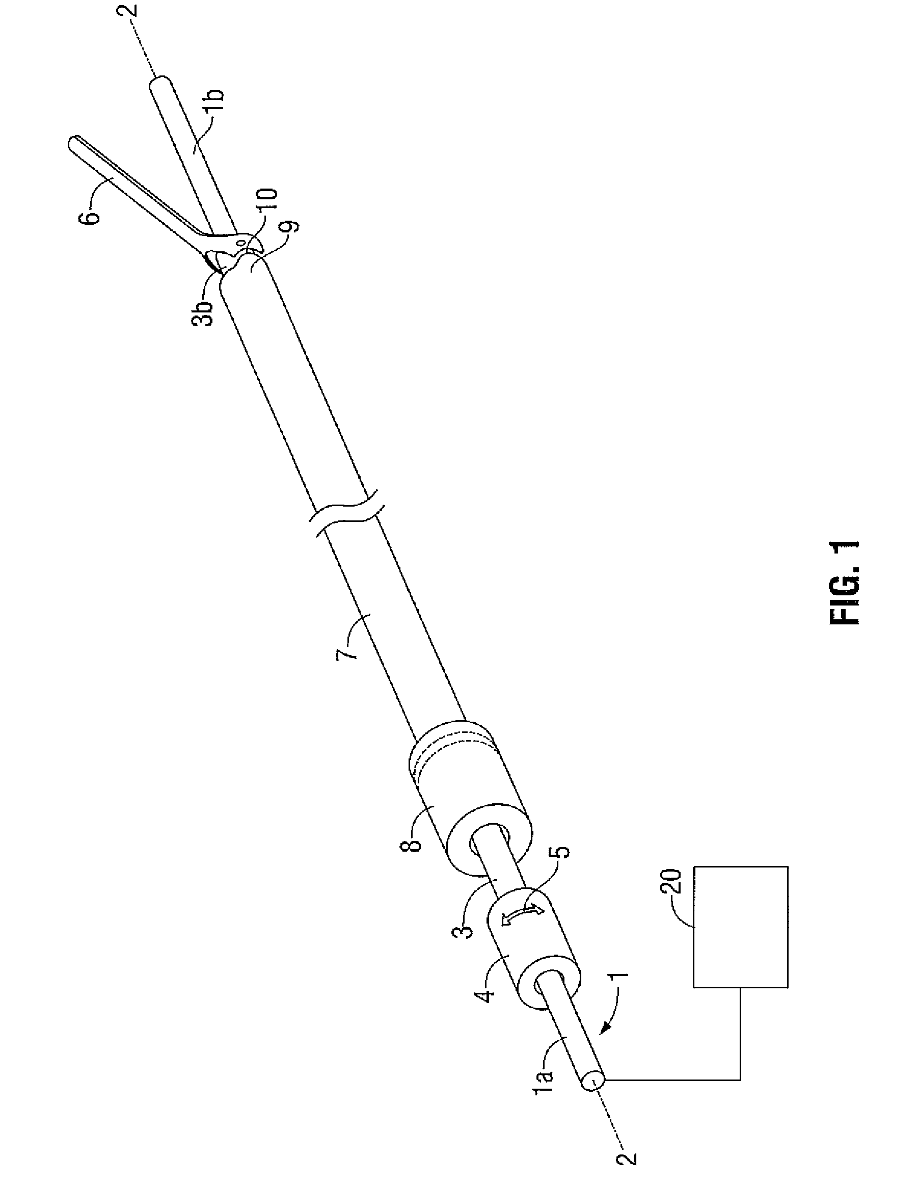
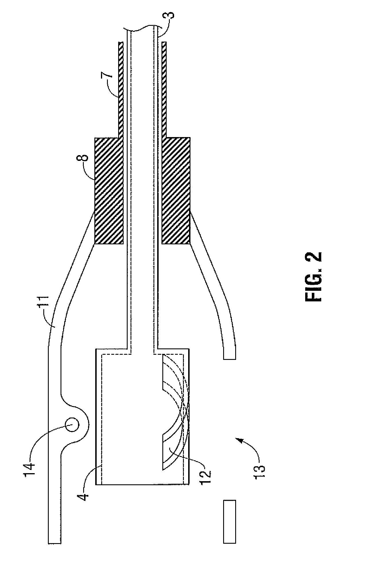
[0041]Embodiments of the presently disclosed ultrasonic surgical system are described in detail with reference to the drawings, in which like reference numerals designate identical or corresponding elements in each of the several views. As used herein, the term “distal” refers to that p...


PUM


Abstract

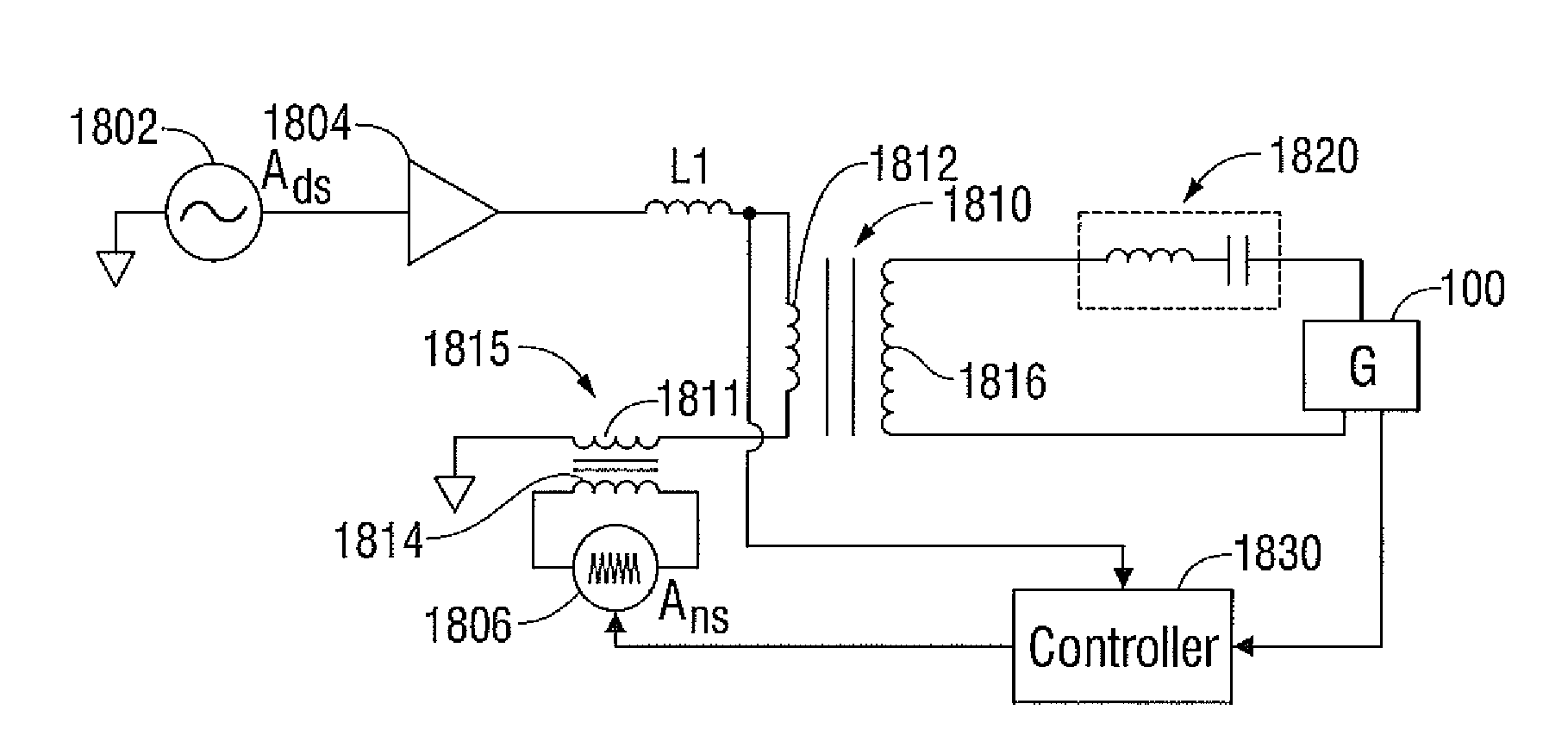
An ultrasonic system is provided that includes an ultrasonic device having an elongated member configured to impart ultrasonic energy to tissue and a resonator configured to impart a frequency to the elongated member. The system also includes an ultrasonic generator configured to supply power to the resonator of the ultrasonic device. The ultrasonic generator has a drive signal generator configured to provide a drive signal, a noise signal generator configure to provide a noise signal, and a controller. The controller receives an output signal from the ultrasonic device and the noise signal from the noise signal generator, calculates a transfer function based on the output signal and the noise signal, and adjusts the drive signal generator based on the calculated transfer function.

Description

BACKGROUND[0001]1. Technical Field[0002]The present disclosure relates to an ultrasonic surgical system. More particularly, but not exclusively, it relates to an ultrasonic surgical system able to achieve precise control of a desired operating point.[0003]2. Background of Related Art[0004]Devices which effectively utilize ultrasonic energy for a variety of applications are well-known in a number of diverse arts. A laparoscopic tool where the surgeon may use a scissors-type, a pistol or trigger type grip outside the body to operate a manipulative, gripping or clamping mechanism at a distal end of the tool within the body is useful for use with ultrasonically operated haemostatic cutting tools. Such haemostatic cutting tools are known from British Patent Number 2333709B, International Patent Applications Numbers PCT / GB99 / 00162 and PCT / GBOO / 01580, and U.S. Pat. No. 5,322,055.[0005]Each of the above identified patents and patent applications describes a surgical tool comprising means to...

Claims


Application Information

Patent Timeline
Patent Type & Authority Patents(United States)
IPC IPC(8): H01L41/08
CPCA61B17/320092B06B1/0253A61N7/02H04B11/00A61B17/22012A61B17/320068A61B2017/00106A61B2017/00146A61B2017/00199A61B2017/00734A61B2017/320072A61B2017/320076B06B2201/76A61B2017/320078A61B2017/320095A61B2017/320069A61B2017/32007A61B2017/320074
Inventor GILBERT, JAMES A.
Owner COVIDIEN LP
Why Eureka
Try Eureka