Apparatus and method for automatic product effect compensation in radio frequency metal detectors

a radio frequency metal detector and product effect technology, applied in the field of radio frequency metal detectors, can solve the problems of inability to achieve the same effect, and inconsistent results between different operators using the same machine, so as to improve the simultaneous sensitivity of the detector and improve the effect of compensating

Active Publication Date: 2012-06-26
THERMO FISHER SCIENTIFIC INC
View PDF16 Cites 34 Cited by
  • Summary
  • Abstract
  • Description
  • Claims
  • Application Information

AI Technical Summary

Benefits of technology

[0013]The current invention relates to improvements in compensating for the effect of a product when the product itself is undergoing inspection by a metal detector by using a time synchronized digital subtraction technique. The present invention improves the simultaneous sensitivity of the detector for metals of different groups by eliminating the need to eliminate signals having a phase component that is also a characteristic phase produced by the product under test. A second aspect of the present invention includes the tracking of trends or changes in the product effect characteristic during the normal flow of multiple products through the metal detector. A change in the average effect generated by the products being examined is used to modify the reference signal employed by the metal detector when the time synchronized digital subtraction technique is active.

Problems solved by technology

A nonzero input coil signal is due to either mechanical imbalances in the construction of the search head, inherent electrical changes in the circuitry such as frequency drift, metal being introduced into the aperture, or the effect of the product itself.
This process is dependent on operator skill and experience, and results in inconsistent results between different operators using the same machine.
There are numerous disadvantages to the metal calibration methods just described.
In general, the operator of the metal detector does not have a clear understanding of the concept and function of the metal detection process.
This lack of understanding leads to misuse of detection calibration controls and necessarily to a reduction in metal detector sensitivity due to improper settings of the metal detector system.

Method used


Image

  • Apparatus and method for automatic product effect compensation in radio frequency metal detectors
  • Apparatus and method for automatic product effect compensation in radio frequency metal detectors
  • Apparatus and method for automatic product effect compensation in radio frequency metal detectors

Examples


Embodiment Construction

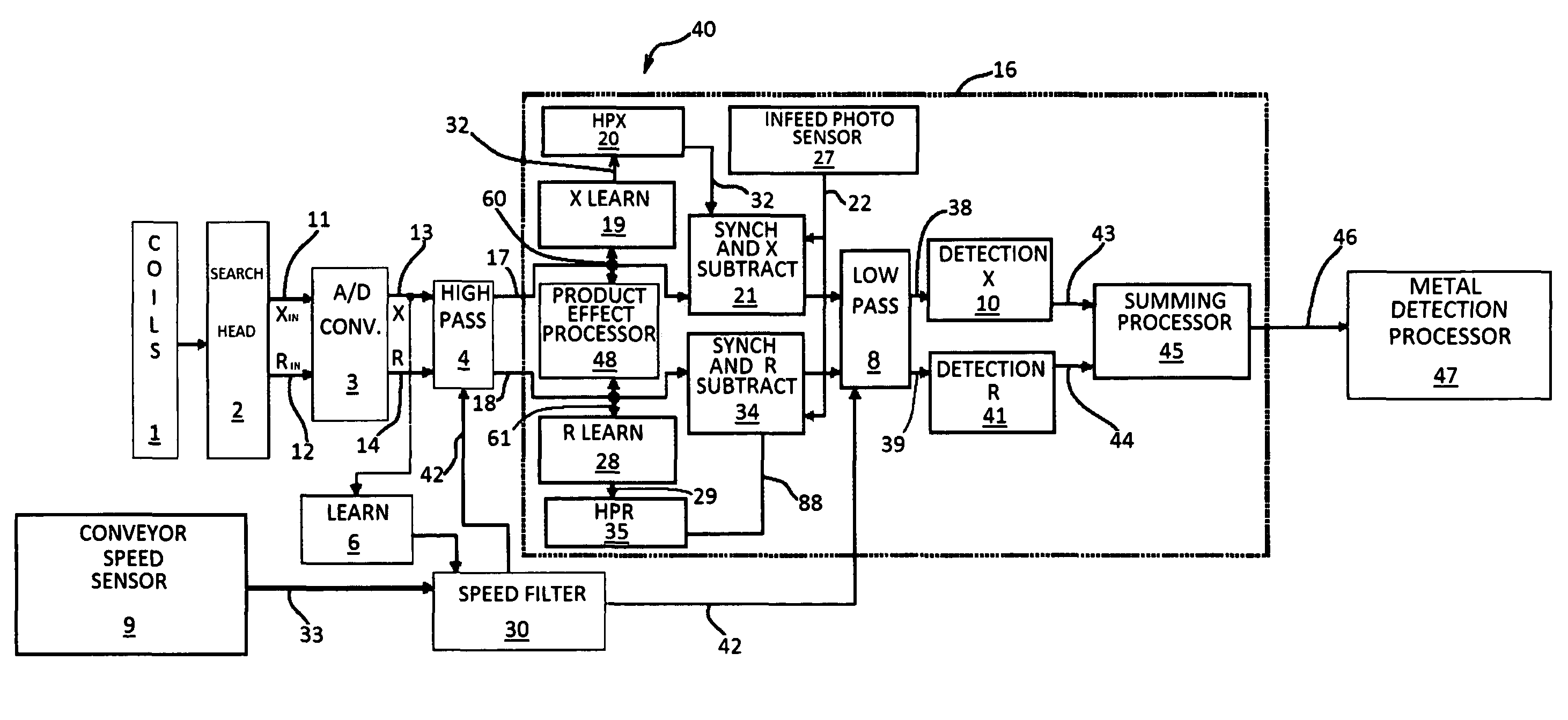
[0019]Referring to FIG. 3, a block diagram of a metal detector constructed according to the principles of the present invention is shown generally at 40. The signals 11 and 12 generated by the search head 2 is processed by the analog to digital converter 3. The resultant digital reactive component signal 13 and resistive component signal 14 are forwarded to a high pass filter 4 for further signal processing. The metal detector 40 includes the capability to measure the instantaneous conveyor speed 33 via conveyor speed sensor 9, the conveyor speed 33 being substantially equal to the speed of any article being introduced into the region of the detector coils 1. The metal detector 40 includes a speed filter 30, which contains a signal processing hardware or software that provides the necessary information to the metal detection algorithm processors 10 and 41 which are capable of determining the presence or absence of a contaminant such as metal.

[0020]The speed filter 30 receives data f...


PUM


Abstract

A metal detector used for identifying contaminants in packages on a conveyor. The detector includes coils a search head and an analog to digital converter generating a reactive signal and a resistive signal in response to the presence of a contaminant. During a learning mode a sample product passes through the metal detector providing a representative product effect signal which is stored by the reactive learn memory and the resistive learn memory. The learn memory values provide a reference value subtracted from each product signal during a normal production cycle, canceling the product effect caused by contaminants in individual packages. The product effect is monitored during successive cycles composed of a series of packages undergoing normal inspection by the metal detector. A tracking processor averages the product effect signal produced by the individual packages and continuously updates a product effect trend signal that is subtracted from each product signal.

Description

BACKGROUND OF THE INVENTION[0001]1. Field of Invention[0002]This invention pertains generally to the field of radio frequency metal detectors, and more particularly to the calibration of such a device.[0003]2. Description of Prior Art[0004]Metal detectors are used in the food processing industry, for example, to detect contaminants within a product. The unwanted material may include very small metallic particles having differing compositions. As seen in FIG. 2, the typical metal detector is housed in an enclosure 26 containing a longitudinal aperture 25 through which the product under test 23 is transported, usually by means of a conveyor belt, in the direction of arrow 24. The metal detector includes a radio frequency transducer or oscillator that radiates a magnetic field by means of some arrangement of coils that serve as a radio frequency antenna. An example of such a metal detector operating in the radio frequency range is disclosed in U.S. Pat. No. 5,994,897, entitled FREQUENC...

Claims


Application Information

Patent Timeline
Patent Type & Authority Patents(United States)
IPC IPC(8): G01R33/12
CPCG01N33/02
Inventor MOSKALENKO, SERGEY A.
Owner THERMO FISHER SCIENTIFIC INC
Why Eureka
Try Eureka