Mobile work platform

Inactive Publication Date: 2012-07-03
TETREAULT JR ADRIEN R
37 Cites 15 Cited by

AI-Extracted Technical Summary

Problems solved by technology

However, the ladder scaffold of the Box Patent does not include a plurality of removable shelves for use in holding tools and or supplies, nor does the ladder scaffold collapse down by folding the two “A” frame members onto the support frame.
However, the A-frame instrument stand of the Hennessey Patent does not include a plurality of removable shelves for supporting tools and/or supplies.
However, the multiple-use cart of the Mace P...

Benefits of technology

[0018]A further object of the mobile work platform is to provide a lightweight platform that can be easily carried.
[0019]A further object of the ...

Abstract

The mobile work platform is a collapsible frame assembly that can support tools, supplies, and workers. The collapsible frame involves two distinct embodiments wherein a first embodiment involves a frame assembly that simply folds flat when not in use, and a second embodiment involves a rotating ladder assembly in conjunction with a frame assembly that can fold flat when not in use. Both embodiments include ladder rungs upon each side to enable climbing upon said device as well as removable scaffolds.

Application Domain

Technology Topic

EngineeringAerial work platform +2

Image

  • Mobile work platform
  • Mobile work platform
  • Mobile work platform

Examples

  • Experimental program(1)

Example

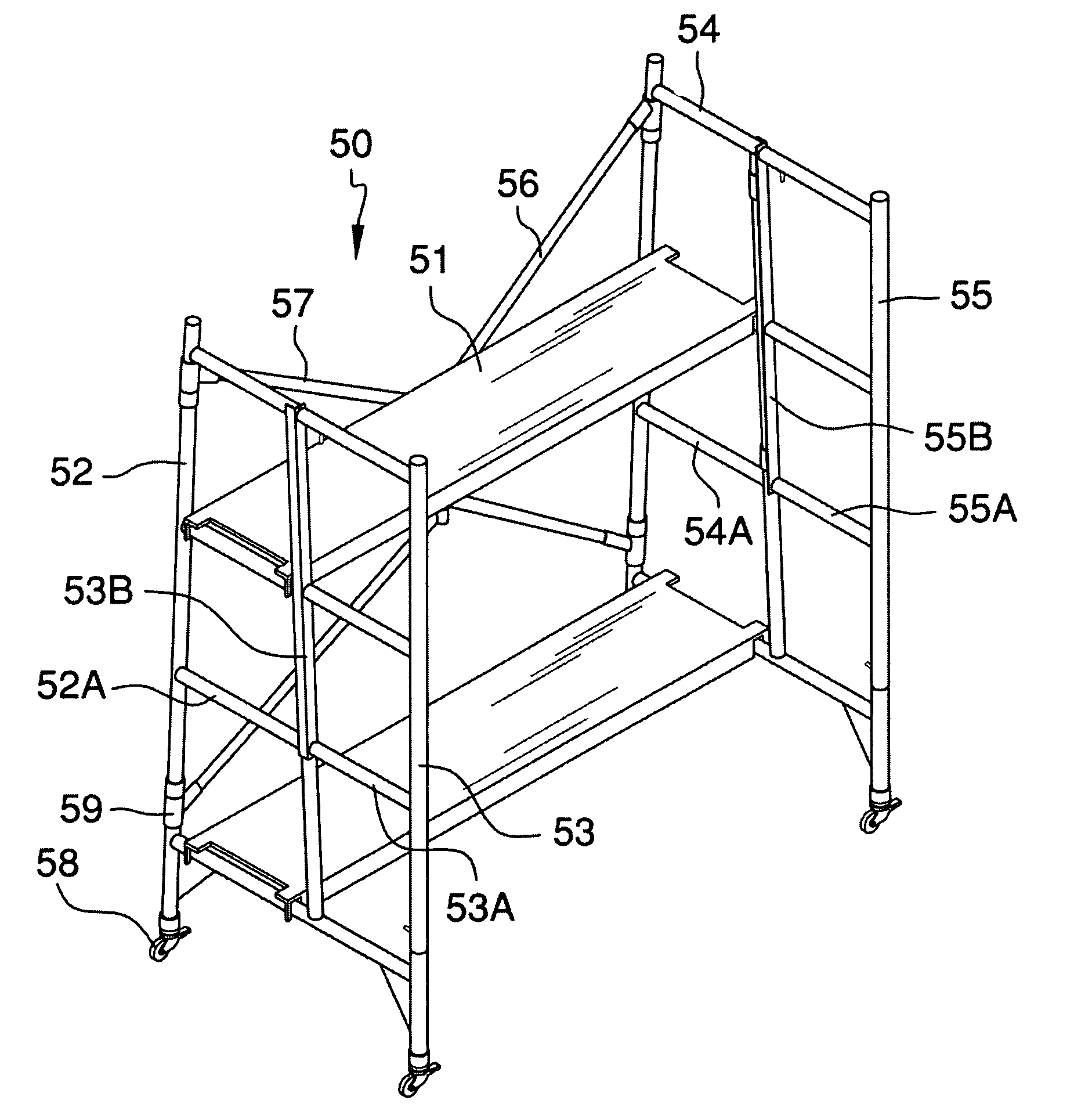
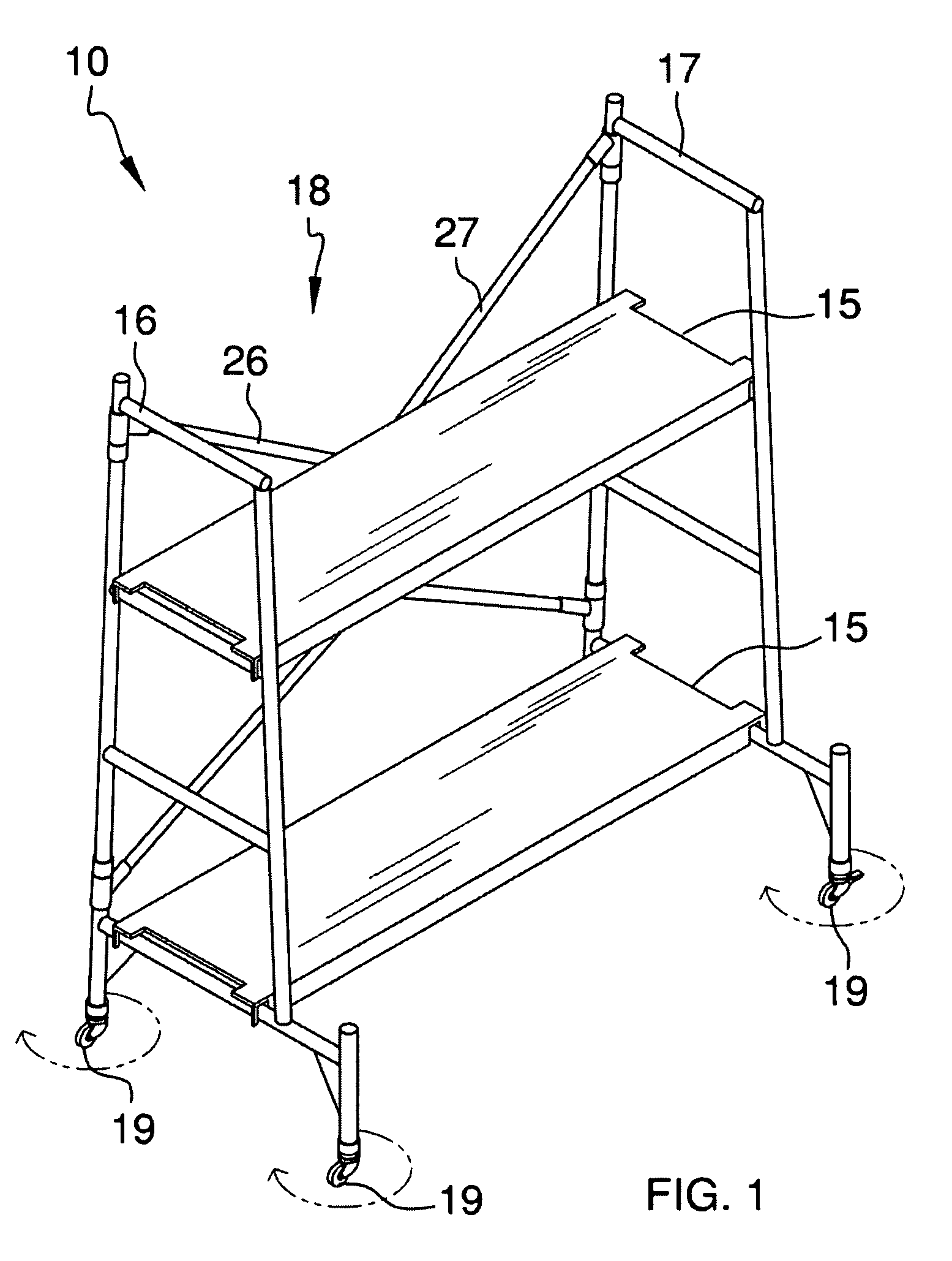
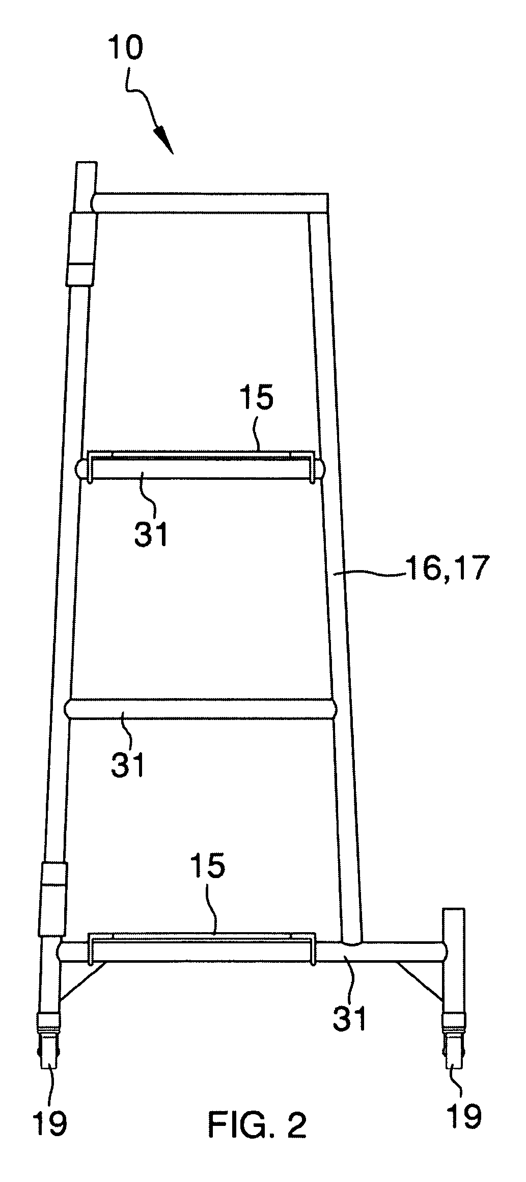
[0039]Detailed reference will now be made to the present invention, examples of which are illustrated in FIGS. 1-5. A first embodiment of a mobile work platform 10 (hereinafter first embodiment) comprises a plurality of removable shelves 15, a left “A” frame 16, a right “A” frame 17, a support frame 18, and a plurality of caster wheels 19.
[0040]The removable shelves 15 have hanging means 25 on each end of each removable shelve 15. The removable shelves are of lightweight construction, but capable of supporting heavy loads. The overall length of the removable shelves 15 shall be dictated by the length of the support frame 18.
[0041]The support frame 18 is made of lightweight, yet durable construction. The support frame 18 comprises a left half 26, and a right half 27. The left half 26 and the right half 27 are connected by a sleeve 28 along the middle region, as depicted in FIG. 3.
[0042]The left half 26 of the support frame 18 is connected along the top and bottom of the left “A” frame 16 by pivot points 30. The right half 27 is connected along the top and the bottom of the right “A” frame 17 by pivot points 30.
[0043]The left “A” frame 16 and the right “A” frame 17 each have a plurality of corresponding horizontal cross members 31 at a variety of heights. The horizontal cross members 31 provide the first embodiment 10 with a plurality of heights for placement of the removable shelves 15, as depicted in FIGS. 1-4
[0044]The left “A” frame 16 and the right “A” frame 17 each have a plurality of the caster wheels 19. The bottom of the left and right “A” frames 16 and 17, have an enlarged horizontal cross member 31, which provides more overall stability for the first embodiment 10.
[0045]When the first embodiment 10 is not in use, the removable shelves 15 are removed. Next, the left “A” frame 16 is folded flat with respect to the left half 26; the right “A” frame 17 is folded flat with respect to the right half 27. Next, the left half 26 and the right half 27 are folded flat with respect to each other, as depicted in FIG. 5.
[0046]The removable shelves 15, the left “A” frame 16, the right “A” frame 17, the left half 26, the right half 27, the sleeve 28, and the pivot points 30 are made from a lightweight material comprising a durable plastic, wood, or metal.
[0047]Referring now to FIGS. 6-13, a second embodiment 50 includes a plurality of shelves 51, a left “A” frame 52, a left rotating ladder 53, a right “A” frame 54, a right rotating ladder 55, a right support frame 56, a left support frame 57, a plurality of caster wheels 58, a plurality of pivot points 59, a pair of upper rotating ladder locking means 61, and a pair of lower rotating ladder locking means 63.
[0048]The plurality of shelves 51, the left “A” frame 52, the right “A” frame 54, the right support frame 56, the left support frame 57, the plurality of caster wheels 58, and the plurality of pivot points 59 all function in the same manner as the first embodiment 10.
[0049]The left rotating ladder 53 and the right rotating ladder 55 operate in the same manner, but in opposite orientations with one another. Angle irons 53B and 55B provide two functions for each rotating ladder, (i) to support hinges 53C and 55C in order to enable horizontal rotational movement of a ladder with respect to the “A” frame, and (ii) to enable the upper locking means an opening for securing the respective ladder in an aligned state with respect to the “A” frame.
[0050]The pair of lower rotating ladder locking means 63 further include a track 63A, a locking bar 63B, a spring 63C. The locking bar 63B is designed to enter the respective “A” frame and lock the rotating ladder 53 in an aligned state with respect to the “A” frame. The rotating ladder 53 can rotate about a front side of the second embodiment 50 by sliding the pin 63 along the track 63A until the locking bar 63B becomes disengaged with the “A” frame. Then, the rotating ladder 53 is rotated about the front of the second embodiment 50.
[0051]The upper rotating ladder locking means 61 includes a pin 61, a track 61A, a locking bar 61B, and a spring 61C. The pair of upper rotating ladder locking means 61 operates in the same manner as the lower rotating ladder locking means 63.
[0052]With respect to the above description, it is to be realized that the optimum dimensional relationship for the various components of the first embodiment 10 and the second embodiment 50, to include variations in size, materials, shape, form, function, and the manner of operation, assembly and use, are deemed readily apparent and obvious to one skilled in the art, and all equivalent relationships to those illustrated in the drawings and described in the specification are intended to be encompassed by the first embodiment 10 and the second embodiment 50.
[0053]It shall be noted that those skilled in the art will readily recognize numerous adaptations and modifications which can be made to the various embodiments of the present invention which will result in an improved invention, yet all of which will fall within the spirit and scope of the present invention as defined in the following claims. Accordingly, the invention is to be limited only by the scope of the following claims and their equivalents.

PUM

no PUM

Description & Claims & Application Information

We can also present the details of the Description, Claims and Application information to help users get a comprehensive understanding of the technical details of the patent, such as background art, summary of invention, brief description of drawings, description of embodiments, and other original content. On the other hand, users can also determine the specific scope of protection of the technology through the list of claims; as well as understand the changes in the life cycle of the technology with the presentation of the patent timeline. Login to view more.

Similar technology patents

Tape measure

InactiveUS20070101599A1Easily carryMaximize it standoutMeasuring tapesTape measureEngineering
Owner:BLACK & DECKER INC

Combination nail polish remover and applicator bottle

ActiveUS20110088710A1Quickly and easily be separateEasily carryCapsWriting implementsSolventApplicator Bottle
Owner:GRACE BEAUTY S R O

Classification and recommendation of technical efficacy words

  • Easily carry
  • Simple design

Protection cover for portable product

InactiveUS20100006468A1Easily carryPortable framesSubstation equipmentInternal zoneAir chamber
Owner:FRUITSHOP INT

Methods and apparatus for femoral and tibial resection

InactiveUS20050055028A1Simple designPrecise and accurate in operationJoint implantsNon-surgical orthopedic devicesFemurCutting guide
Owner:PUGET BIOVENTURES
Why Eureka
Try Eureka