Water hammerless valve

a technology of hammerless valves and valve parts, applied in the direction of valve details, valve arrangements, valve members for absorbing fluid energy, etc., can solve the problems of complicated operation, pressure wave, and difficulty for operators to take immediate action in an emergency situation

Inactive Publication Date: 2012-07-03
FUJIKIN INC
View PDF11 Cites 33 Cited by
  • Summary
  • Abstract
  • Description
  • Claims
  • Application Information

AI Technical Summary

Benefits of technology

[0017]In another embodiment of the present invention, the control device enables the stepping motor to stop when the vertical movement component moves upward and the bottom of the component reaches its predefined position higher than the highest position of the upper stem. Thus it is possible to stop the vertical movement component automatically when the vertical movement component is placed in the predefined position not to contact with the upper stem.
[0018]Yet in another embodiment of the present invention, a thread mechanism is provided to connect the rotation shaft of the stepping motor and the vertical movement component. Thus it enables the stem not to move upward when a big upward pressure is provided in the stem to limit the fluid channel opening without any failure.

Problems solved by technology

The water hammer causes rapid increase in pressure along upstream from the valve closing point, which results in a pressure wave.
However, the technique disclosed therein requires to press the stem with the bolt manually screwed by operators in the field, which results in complicated operation.
It is difficult for operators to take immediate responses in an emergency situation.
This does not prevent the water hammer pressure from opening the fluid channel when the valve is closed.

Method used


Image

  • Water hammerless valve
  • Water hammerless valve
  • Water hammerless valve

Examples


Embodiment Construction

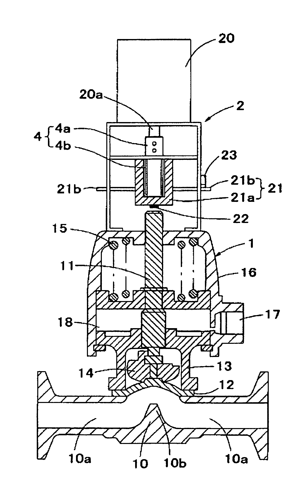
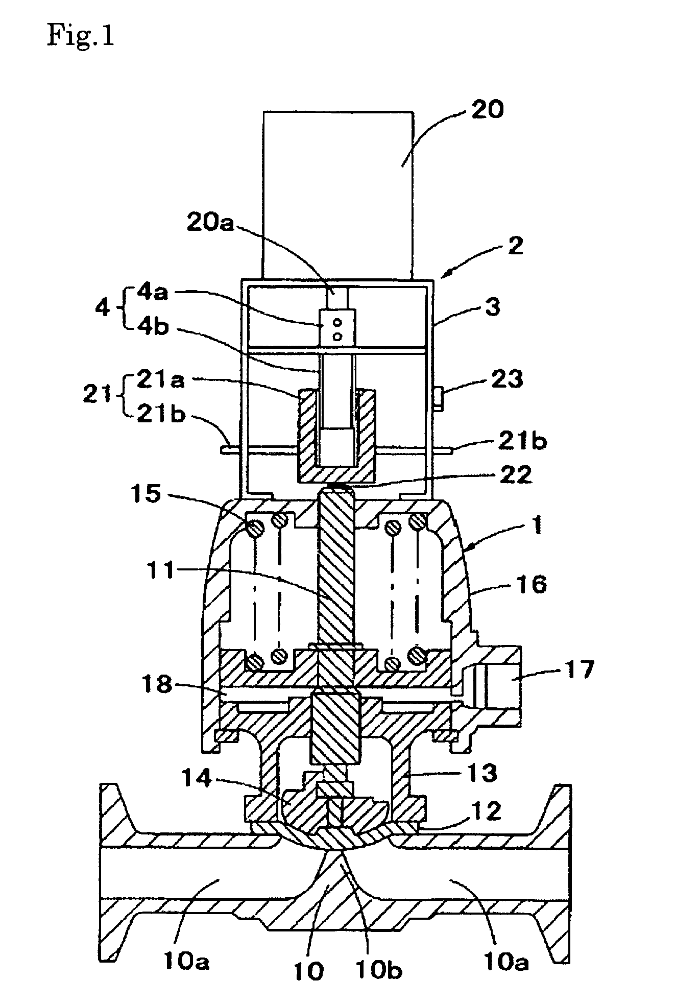
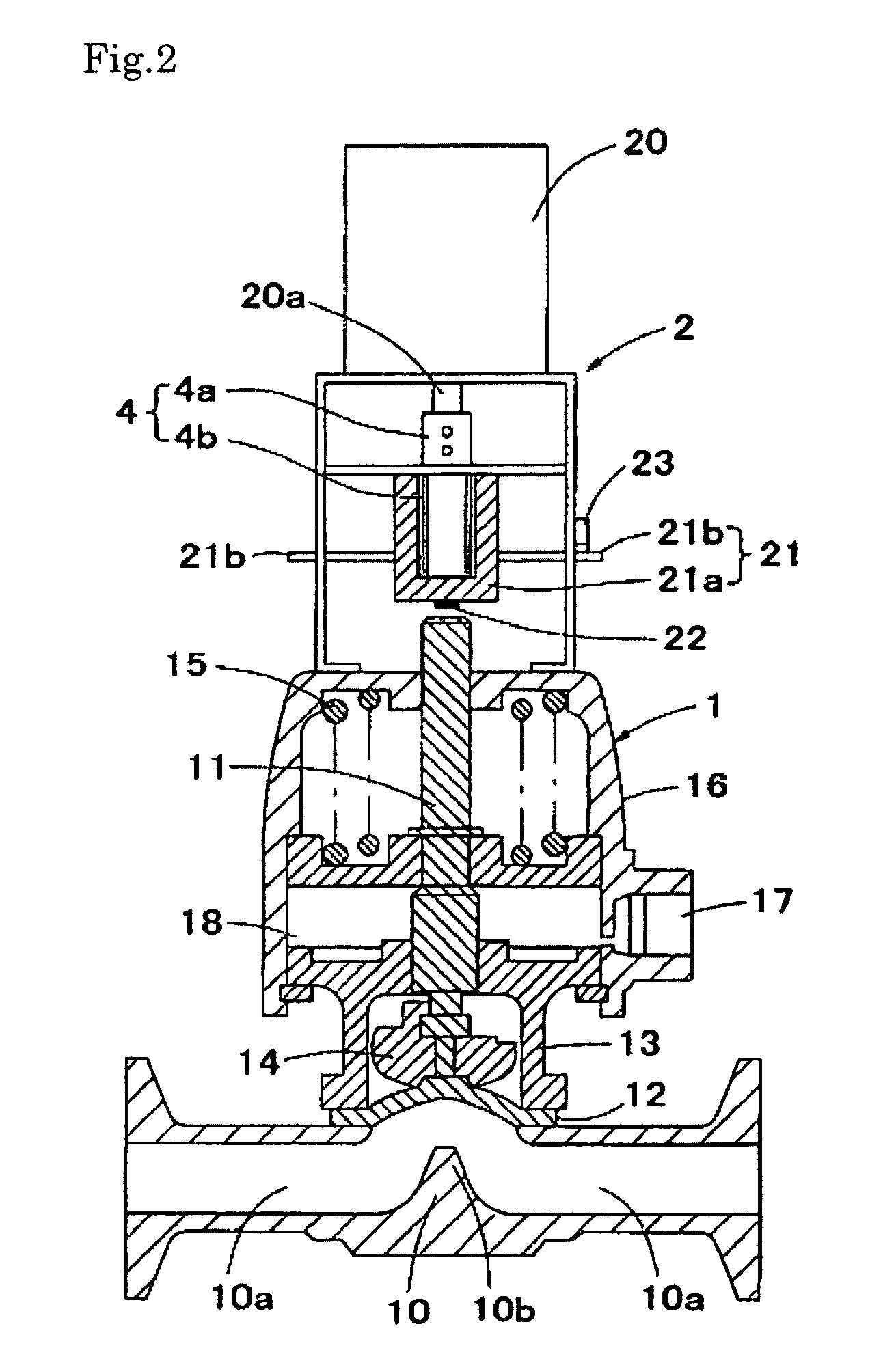
[0026]FIGS. 1 and 2 are schematic views of the whole water hammerless valve according to the present invention. FIG. 1 shows the valve in the closed position, and FIG. 2 shows the valve in the opened position.

[0027]The water hammerless valve according to the present invention comprises a pneumatically-operating valve (1) provided on the upper valve assembly for opening and closing a fluid channel through a pneumatic actuator operation, and a limiting mechanism (2) for interfering upward movement of the valve disc when the water hammer occurs.

[0028]The pneumatically-operating valve (1) has a known structure comprising a valve assembly and a pneumatic actuator. The valve assembly includes a valve body (10), stem (11), valve disc (12), bonnet (13) and compressor (14). The pneumatic actuator includes a spring (15) and cap (16) provided on the upper part of the valve assembly. A fluid channel (10a) and valve seat (10b) are provided on the valve body (10). The cap (16) is provided with an...


PUM


Abstract

A water hammerless valve includes a pneumatically-operated valve having a valve disc for opening and closing a fluid channel by moving upward and downward through a pneumatic actuator operation, and a limiting mechanism for interfering with upward movement of the valve disc when the water hammer occurs. The limiting mechanism includes a stepping motor including a rotation shaft fixed on the upper actuator; a vertical movement component connected to the rotation shaft for moving upward and downward via rotation of the rotation shaft; a lower detecting component for detecting the fact that the vertical movement component contacts the upper end of a stem when the lower detecting component moves downward; and a control device for rotating the stepping motor, for controlling the air supply, and for transmitting a stop signal to the stepping motor when the lower end of the lower detecting component detects the fact.

Description

RELATED APPLICATIONS[0001]This application is Continuation-In-Part Application of International Application No. PCT / JP2006 / 315179, filed on Jul. 31, 2006, which claims priority of Japanese Patent Application No. 2005-368730, filed on Dec. 21, 2005, the entire content and disclosure of the preceding applications are incorporated by reference into this application.BACKGROUND OF THE INVENTION[0002]1. Field of the Invention[0003]This invention relates to a water hammerless valve with a pneumatically-operating valve for opening and closing the fluid channel through the pneumatic actuator operation to control opening of a fluid channel caused by the occurrence of a water hammer.[0004]2. Description of the Related Art[0005]It is well known that the water hammer results from a sudden closure of a valve placed in a pipe in which fluid such as water passes. The water hammer causes rapid increase in pressure along upstream from the valve closing point, which results in a pressure wave. The wav...

Claims


Application Information

Patent Timeline
Patent Type & Authority Patents(United States)
IPC IPC(8): F16K31/122F16K51/00
CPCF16K31/046F16K37/00F16K47/02F16K37/0025
Inventor MIYAGAWA, HIDEYUKISHIMIZU, YUKIINOUE, MIKIO
Owner FUJIKIN INC
Why Eureka
Try Eureka