Pipe coupling

a technology of pipe joints and couplings, applied in the direction of hose connections, sleeve/socket joints, mechanical equipment, etc., can solve the problems of high cost, high current and likely continuing usage rates, and similar current and likely continuing high usage rates, so as to reduce the amount of material required, reduce the cost of material consumption, and reduce the effect of reducing the number of parts

Inactive Publication Date: 2012-07-03
DELMER DAN W C
View PDF35 Cites 4 Cited by
  • Summary
  • Abstract
  • Description
  • Claims
  • Application Information

AI Technical Summary

Benefits of technology

[0012]It is, therefore, an object of the invention to provide apparatus and methods for joining pipes to each other, using the “shape memory” or “material memory” property of the pipe. Persons of ordinary skill in the art will understand that the invention can be practiced with a wide variety of pipe materials having a wide range of cross-sectional shapes, in which one or the other or both of a female end and a male end of pipes can be temporarily deformed to permit insertion of the male end into the female end. This provides a joint that is simple to manufacture and install, and can be more secure than prior art joints.
[0013]Persons of ordinary skill in the art will also understand that, although much of the description herein focuses on temporary deformation of a female end, alternative embodiments can include temporary deformation (compression) of the male end, or temporary deformation of both the male and female ends. Moreover, although certain embodiments discussed herein involve some delay between the initial deformation of the pipe end and the assembly of the male and female ends with each other, other embodiments may involve simply forcing the male and female ends into engagement without “prior” deformation of either end. In such applications, the “temporary deformation” discussed herein preferably occurs during the relatively brief process of assembling the pipe segments to each other.
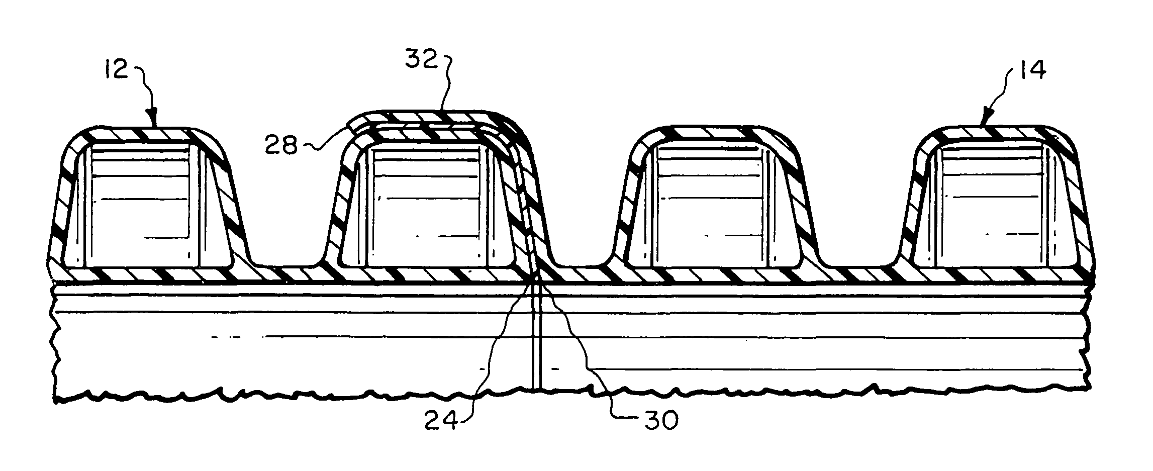
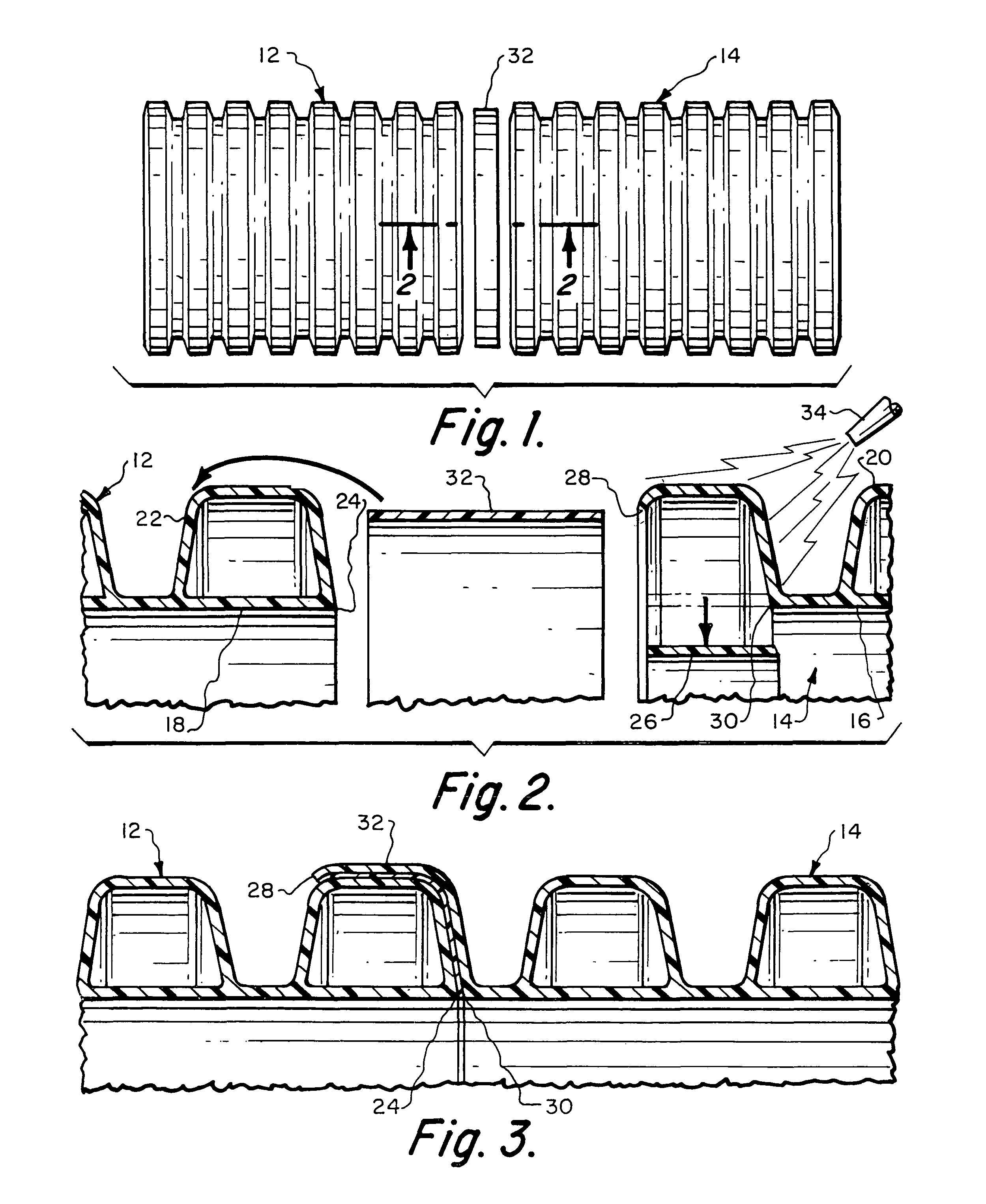
[0014]Another object of my invention is the provision of apparatus and methods of the aforementioned character, in which a plurality of pieces of pipe includes a first piece of pipe fabricated with a cross-sectional sidewall pattern along its length that is similar in size and shape to the cross-sectional sidewall pattern of a second piece of pipe, the first piece having a first end that is temporarily deformed to function as a female end for receiving a non-deformed end of the second piece of pipe, the temporary deformation being both sufficiently large to permit the insertion of the non-deformed end of the second piece of pipe but also sufficiently small to ensure that the material memory of the first end returns the first end toward its original non-deformed configuration with sufficient compressive force to grip the second end and prevent its inadvertent removal from engagement with the first end. Engagement elements can be formed within the pipes' cross-sectional sidewall pattern to act between the first and the second pieces of pipe to increase the force necessary to disengage the pipe pieces from each other following assembly. Among the many alternative embodiments of the invention, the pipe sidewall pattern can include a corrugated exterior surface (with or without an internal non-corrugated liner element), can be non-corrugated with a generally constant radius along its length (a “mono-walled” pipe), or can be of other patterns.
[0015]A further object of my invention is the provision of apparatus and methods of the aforementioned character, in which the first piece of pipe includes a second end remote from the first end, the second end also being temporarily deformed to function as a female end for receiving a corresponding non-deformed end of a third piece of pipe, the third piece of pipe having a cross-sectional sidewall pattern along its length that is similar in size and shape to the cross-sectional sidewall pattern of the first and second pieces of pipe. One or more sealing elements can be positioned between confronting surfaces of the first and second pieces of pipe to help provide a watertight seal therebetween. Adhesive can be placed between confronting surfaces of the first and second pieces of pipe to bond the first and second pieces to each other upon insertion of the second piece into the female end of the first piece.
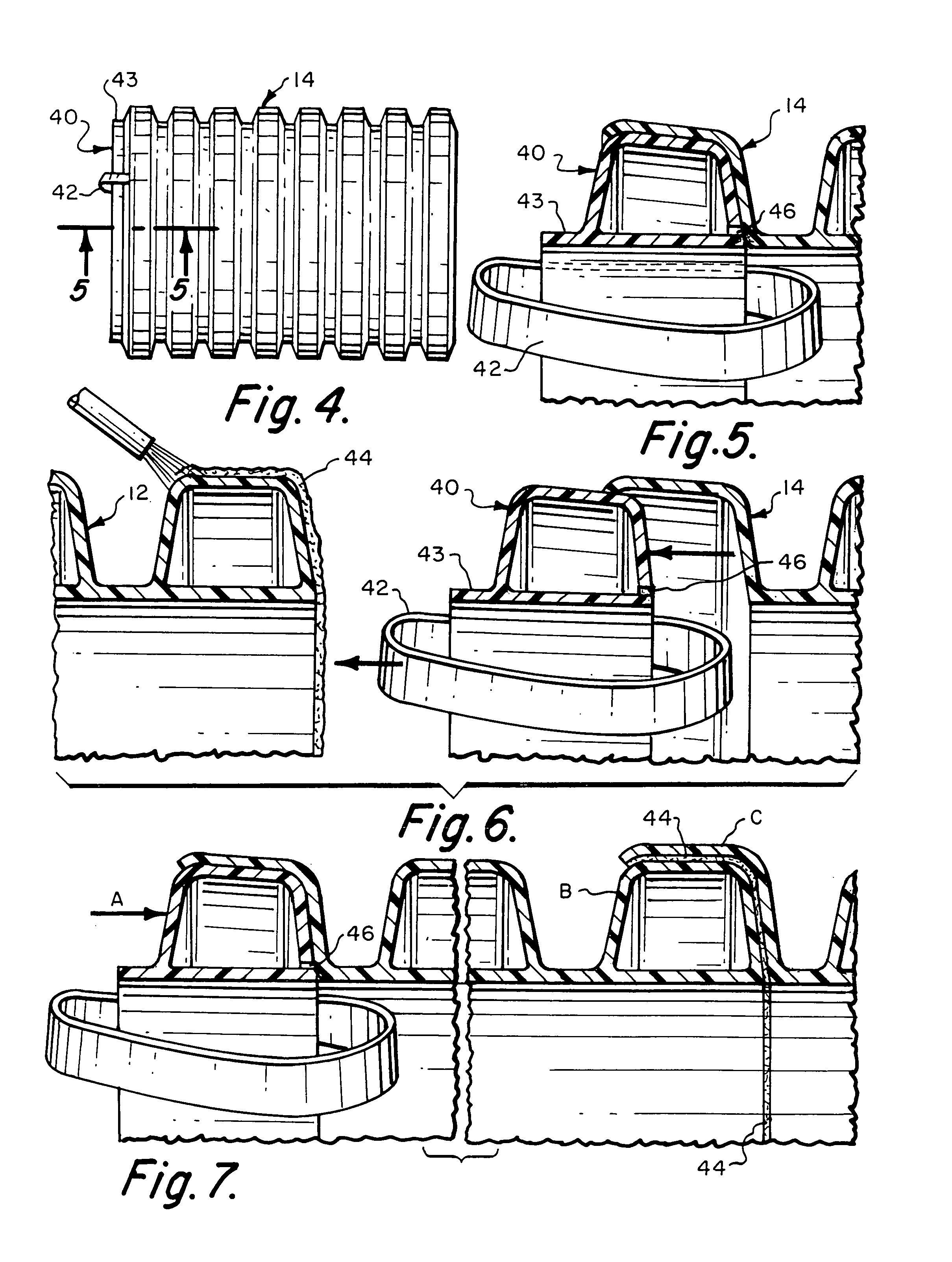
[0016]Yet another object of my invention is the provision of apparatus and methods of the aforementioned character, including providing a stretching tool for use in connection with the apparatus and methods. Among the many alternative embodiments, the tool can be a heating element to soften the end to be deformed, or can deform the end mechanically. In the latter approach, a channel can be provided in the tool, into which an edge of the first piece of pipe can be inserted in its originally fabricated shape, with the tool including means to temporarily stretch or deform the edge to the female end configuration capable of receiving the non-deformed end of the second pipe piece. The mechanical tool embodiments can include a plurality of rollers positionable along the inside and outside surfaces of the eventual female end of the first piece of pipe, and can further include means for exerting force to act between the rollers and the eventual female end to deform the female end from its originally fabricated shape.
[0017]A still further object of my invention is the provision of apparatus and methods of the aforementioned character, including a temporary stretch-holding device for use in connection with the apparatus and methods. Among the many alternative embodiments, the device can include a first portion for temporary insertion into the deformed female end of the first pipe piece. Preferably, the first portion is sized and configured to retain a sufficient degree of the deformation of the female end so that, upon the removal of the device from the female end, the non-deformed end of the second piece of pipe may be inserted into engagement with the female end. The device can also include a second portion to assist in desired removal of the device from its temporary insertion into the deformed female end.

Problems solved by technology

Joining the pipe pieces to each other can be an important, time-consuming, and costly process, especially for large-diameter, long pipes where leakage at the joint must be controlled or minimized.
Other plastic pipes have similar current and likely continuing high usage rates.
Current joints are unsatisfactory / unreliable for such applications, are expensive, or both.
Among other things, the approach shown in that patent is costly to manufacture and install, and can be unwieldy to handle.
These dimensional variations contribute to the unreliability of current “pressure resisting” couplings and bell and spigot designs.
The present methods are so unreliable that a common term used to describe the products is “soil tight” rather than “watertight”.
Because those ASTM requirements are for controlled testing conditions and because present coupling technology is so “leaky”, if a contract requires post-installation pressure testing of the installed pipe, few if any companies will even bid to use plastic corrugated drainpipe on the project, and instead will only bid to use only clay or some other type of pipe.
Neither this approach or the one discussed in the previous paragraph provide any way to join the ends of lengths of similarly sized and shaped pipe pieces, but instead require more complicated manufacturing and installation (the pieces are not bi-directional, have to be drilled through the sidewall, etc.).
Such an approach is not usable in plastic pipe that has “shape memory”(such as larger diameter or thicker-walled, less pliable pipe) because, among other things, those “shape memory” pipes typically are much more rigid than the tubing of that '233 patent and cannot be flattened (because it would deform the pipe beyond its “shape memory” or yield point).
Other types of pipe are commonly joined by similarly relatively complex or expensive technologies.
This method is clever and effective but requires sophisticated costly and cumbersome equipment on the job site.

Method used


Image

  • Pipe coupling
  • Pipe coupling
  • Pipe coupling

Examples


Embodiment Construction

[0042]Several preferred embodiments of the invention are illustrated generally in the attached drawings. In general terms, the invention utilizes the “shape memory” or the “material memory” elastic property of certain pipe sidewalls to form a joint with other similarly sized and shaped pipes. Persons of ordinary skill in the art will understand that the invention can be practiced with a broad range of materials (any which have a sufficient stretchability in relationship to the sidewall thickness and circumference of the pipe), and for a broad range of sidewall cross-sections.

[0043]In the embodiment of FIGS. 1-3, two pipe elements 12 and 14 have a generally corrugated cross-section, similar to the corrugated tubing B described in U.S. Pat. No. 5,326,138, which is incorporated herein by reference. The pipe elements 12 and 14 have interior “flat” liner portions 16 and 18 and exterior corrugated portions 20 and 22.

[0044]Preferably, a male end is provided on element 12, such as by formin...


PUM

PropertyMeasurementUnit
diameteraaaaaaaaaa
lengthsaaaaaaaaaa
effective diameteraaaaaaaaaa

Abstract

Apparatus and methods for joining similar pieces of plastic pipe includes using the shape memory of the pipe pieces to slightly deform a “female” end to permit insertion therein of a non-deformed male end. The deformation is sufficient to permit the insertion but not so large as to preclude the substantially complete “recovery” of the female end's shape and size, using the “shape memory” of the pipe material. Embodiments include, without limitation, single-walled (or mono-walled) pipe, pipe formed from multiple material layers, corrugated pipe, flat-walled pipe, and others. Preferred tools and apparatus are disclosed for stretching the female end and maintaining the desired stretch during transportation and storage, for sealing the joint (via adhesive/sealant, flange gasket, O-ring, or the like), and for further protecting the resulting joint.

Description

BACKGROUND OF THE INVENTION[0001]This invention relates generally to pipe joints, and more specifically to methods and apparatus for joining similar pieces of plastic pipe to each other where the pipe is made of material that has a “shape memory” that permits slight temporary deformation of the pipe.[0002]Plastic pipe, including corrugated drainpipe, is used extensively in the United States and foreign countries. In many applications, similarly sized and shaped lengths of pipe are fabricated and transported to installation sites, where they are assembled with each other to form a desired extended flowpath for certain fluids. The size and shape of the pipes, as well as the fluids handled and the installation sites, can vary widely. By way of example, corrugated polyethylene drainpipe is commonly 12″ diameter and 20′ long. Joining the pipe pieces to each other can be an important, time-consuming, and costly process, especially for large-diameter, long pipes where leakage at the joint ...

Claims


Application Information

Patent Timeline
Patent Type & Authority Patents(United States)
IPC IPC(8): F16L21/00F16L25/00F16L25/10
CPCF16L25/0063F16L25/10Y10S285/903Y10S285/921Y10T29/4987F16L9/12F16L13/147F16L39/00F16L2013/145
Inventor DELMER, DAN W. C.
Owner DELMER DAN W C
Why Eureka
Try Eureka