Speed control device for vehicle

a technology for controlling devices and vehicles, applied in process and machine control, instruments, navigation instruments, etc., can solve problems such as discomfort of drivers, and achieve the effect of suppressing vehicles and less discomfor

Inactive Publication Date: 2012-07-03
AISIN AW CO LTD
View PDF9 Cites 4 Cited by
  • Summary
  • Abstract
  • Description
  • Claims
  • Application Information

AI Technical Summary

Benefits of technology

[0014]In view of the circumstances described above, it is an object of the present invention to provide a speed control device for a vehicle that is capable of achieving speed control conforming to the feeling of the driver and giving little sense of discomfort to the driver when the vehicle passes through two successive curves.
[0020]Therefore, when the vehicle passes through the two successive curves, the vehicle can be accelerated, after being decelerated to the appropriate vehicle speed for the first curve, to the speed equal to or more than the appropriate vehicle speed that is the higher of the appropriate vehicle speeds for the first and the second curves, and then can be decelerated to the appropriate vehicle speed for the second curve. As a result, it is possible to achieve the speed control conforming to the feeling of the driver and giving little sense of discomfort to the driver.
[0021]It is preferable that the above-described speed control device according to the second aspect of the present invention be structured so that the vehicle speed limit is set to a value equal to the appropriate vehicle speed that is the higher of the two appropriate vehicle speeds if the curve-to-curve distance is a predetermined value or less. With this structure, it is possible to suppress the vehicle from being unnecessarily accelerated between the curves if the two curves are close to each other (if the curve-to-curve distance is small).
[0022]In addition, in the above-described speed control device according to any one of the first and the second aspects of the present invention, it is preferable that the vehicle speed limit be set to be larger as the curve-to-curve distance is larger. With this structure, it is possible to increase the maximum vehicle speed between the curves as the curve-to-curve distance is larger, thereby enabling to achieve the speed control further conforming to the feeling of the driver and giving little sense of discomfort to the driver.
[0024]With this structure, when the driver performs an accelerating operation while the vehicle is running along the two successive curves, the vehicle speed can be made higher than that when the driver performs no accelerating operation. Consequently, it is possible to achieve the speed control conforming to the requirement of the driver to accelerate the vehicle and giving less sense of discomfort to the driver.
[0025]When the accelerating operation by the driver is taken into account in this manner, it is preferable that the target vehicle speed determination unit be structured so as to determine the target vehicle speed so that an increment of the target vehicle speed from the target vehicle speed when the operating amount is zero does not exceed a predetermined upper limit. With this structure, it is possible to suppress the vehicle from being unnecessarily accelerated when the vehicle runs along the two successive curves.

Problems solved by technology

As a result, if, for example, the distance between the curves is long, the driver may feel uncomfortable due to lack of acceleration and so on, because the vehicle is not accelerated between the curves.
As a result, if, for example, the distance between the curves is long, the driver may feel uncomfortable due to lack of acceleration and so on, because the vehicle cannot be accelerated sufficiently between the curves, similarly to the case of the device described in Japanese Patent Application Publication No.

Method used


Image

  • Speed control device for vehicle
  • Speed control device for vehicle
  • Speed control device for vehicle

Examples


Embodiment Construction

[0044]An embodiment of a speed control device for a vehicle according to the present invention will be described below with reference to the accompanying drawings.

[0045](Structure)

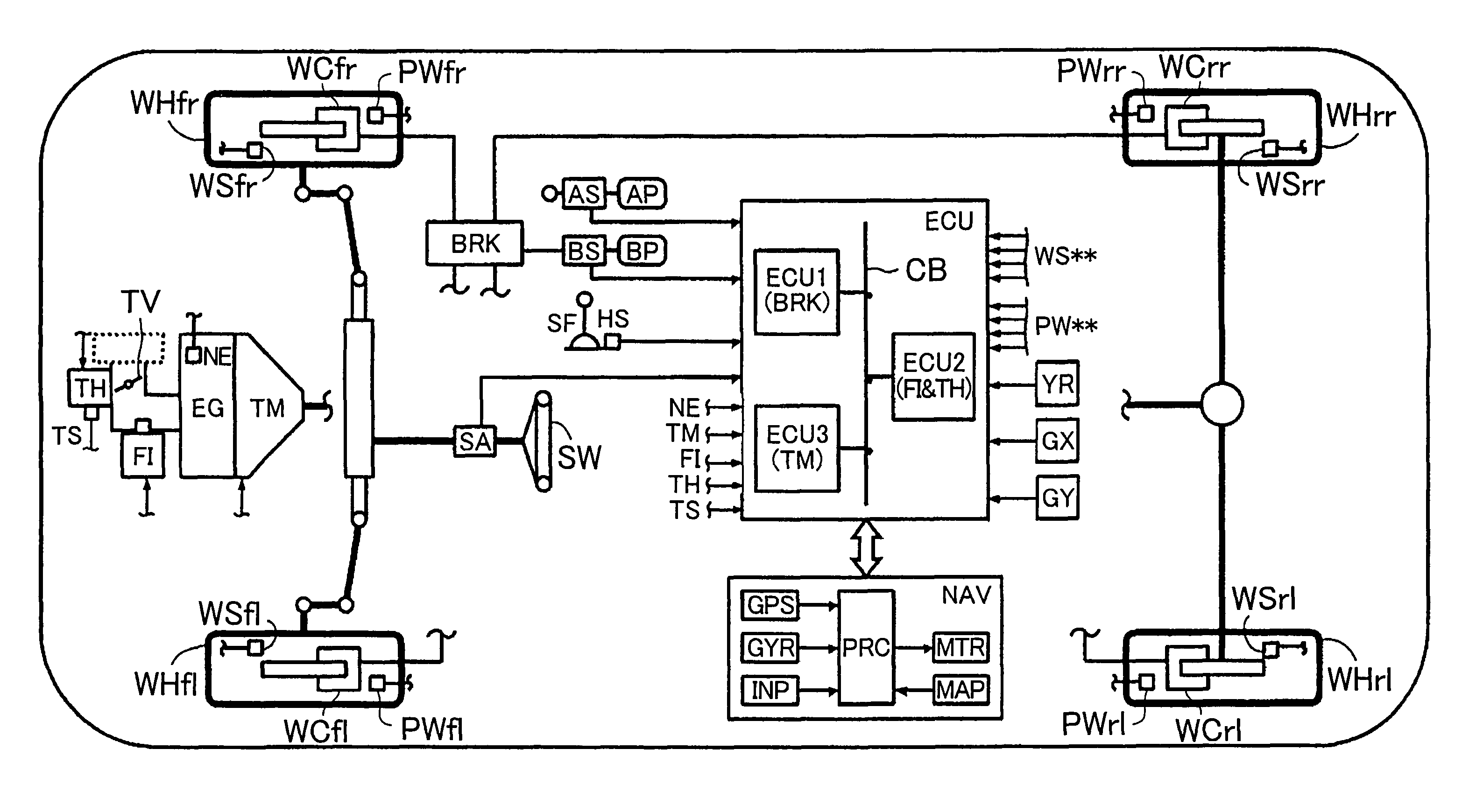
[0046]FIG. 1 shows a schematic structure of a vehicle equipped with a speed control device (hereinafter referred to as “present device”) according to an embodiment of the present invention. The present device is equipped with an engine EG serving as a power source of the vehicle, an automatic transmission TM, a brake actuator BRK, an electronic control unit ECU, and a navigation device NAV.

[0047]The engine EG is, for example, an internal combustion engine. That is, an opening of a throttle valve TV is regulated by a throttle actuator TH in response to operation of an accelerator pedal (acceleration operating member) AP by a driver. A fuel injection actuator (injector) FI injects fuel of a quantity proportional to the quantity of intake air regulated depending on the opening of the throttle valve TV. As a r...


PUM


Abstract

A speed control device includes: a continuous curve acquiring unit that acquires curve shapes and positions of two successive curves in advance of the vehicle; a curve-to-curve distance calculating unit that calculates distance between the two curves based on curve shapes and positions of the two curves; a selection unit that selects, based on the curve shapes, the curve shape of the curve having the larger radius of curvature; a vehicle speed limit setting unit that sets, based on the curve-to-curve distance and selected curve shape, a vehicle speed limit for travel between the two curves; a target vehicle speed determination unit that determines, based on vehicle location, the curve shapes and positions, and the vehicle speed limit, a target vehicle speed for traveling the two curves; and a vehicle speed control unit that controls vehicle speed based on the target and detected vehicle speeds.

Description

[0001]The disclosure of Japanese Patent Application No. 2008-249545 filed on Sep. 29, 2008, including the specification, drawings and abstract is incorporated herein by reference in its entirety.BACKGROUND OF THE INVENTION[0002]The present invention relates to a speed control device for a vehicle, and more particularly to a speed control device for a vehicle that controls a speed at which the vehicle runs along two successive curves.DESCRIPTION OF THE RELATED ART[0003]Conventionally, there is widely known a speed control device for a vehicle that performs speed control (automatic cruise control) to maintain a speed of the vehicle (vehicle speed) at a vehicle speed that has been set, for example, by a driver. There is also known a device that decelerates and adjusts the vehicle speed when the vehicle runs along two successive curves during this automatic cruise control.[0004]For example, in a device described in Japanese Patent Application Publication No. JP-A-2002-362183, during the...

Claims


Application Information

Patent Timeline
Patent Type & Authority Patents(United States)
IPC IPC(8): B60T8/32B60K31/00B60T7/12B60W10/04B60W10/06B60W10/10B60W10/18B60W10/188B60W30/00B60W30/02B60W30/14F02D29/02G08G1/16
CPCB60W10/08B60W10/10B60W10/184B60W30/14B60W30/18009B60W30/18145B60W50/0097B60W2510/0604B60W2510/0638B60W2520/105B60W2520/125B60W2520/14B60W2520/28B60W2540/10B60W2540/12B60W2540/16B60W2540/18B60W2720/103B60W2552/20B60W2552/30B60W2556/50Y02T10/72
Inventor MIYAJIMA, TAKAYUKIYASUI, YOSHIYUKI
Owner AISIN AW CO LTD
Why Eureka
Try Eureka