
Centralized scanner database with optimal definition distribution using network queries

a scanner database and network query technology, applied in the field of computer security, can solve the problems of increasing the number of new known malware, increasing the difficulty of updating, and increasing the number of known malwar

Active Publication Date: 2012-07-10
CA TECH INC
View PDF16 Cites 13 Cited by
  • Summary
  • Abstract
  • Description
  • Claims
  • Application Information

AI Technical Summary

Benefits of technology

This approach minimizes storage and bandwidth usage, reduces network traffic, and ensures reliable malware detection without increasing vulnerability to re-emerging threats, by using filters to quickly identify potential malware and retrieving full definitions only when necessary.

Problems solved by technology

Malware such as computer viruses, worms, Trojan horses, and spyware pose a constant threat to modern computer systems.
In recent years, the number of new known malware has increased dramatically, making the distribution of updates an increasingly challenging problem.
The frequent updates can create data overload problems for client machines that must constantly receive and store new definitions while continuing to store and maintain all of the older definitions.
This is particularly problematic for client machines with limited physical memory such as, for example, Automated Teller Machines (ATMs), or for machines with limited network bandwidth.
Furthermore, distributing large numbers of definitions to client machines results in significant costs to the definition distributers.
However, this approach leaves the client vulnerable to attack should these older threats reappear.
However, while this approach reduces local storage requirements, it significantly increases network traffic between the client and server and does not provide significant improvement in overall performance and cost.

Method used


Image

  • Centralized scanner database with optimal definition distribution using network queries
  • Centralized scanner database with optimal definition distribution using network queries
  • Centralized scanner database with optimal definition distribution using network queries

Examples


Embodiment Construction

[0018]Reference will now be made in detail to several embodiments, examples of which are illustrated in the accompanying figures. It is noted that wherever practicable similar or like reference numbers may be used in the figures and may indicate similar or like functionality. The figures depict embodiments for purposes of illustration only. One skilled in the art will readily recognize from the following description that alternative embodiments of the structures and methods illustrated herein may be employed without departing from the principles described herein.

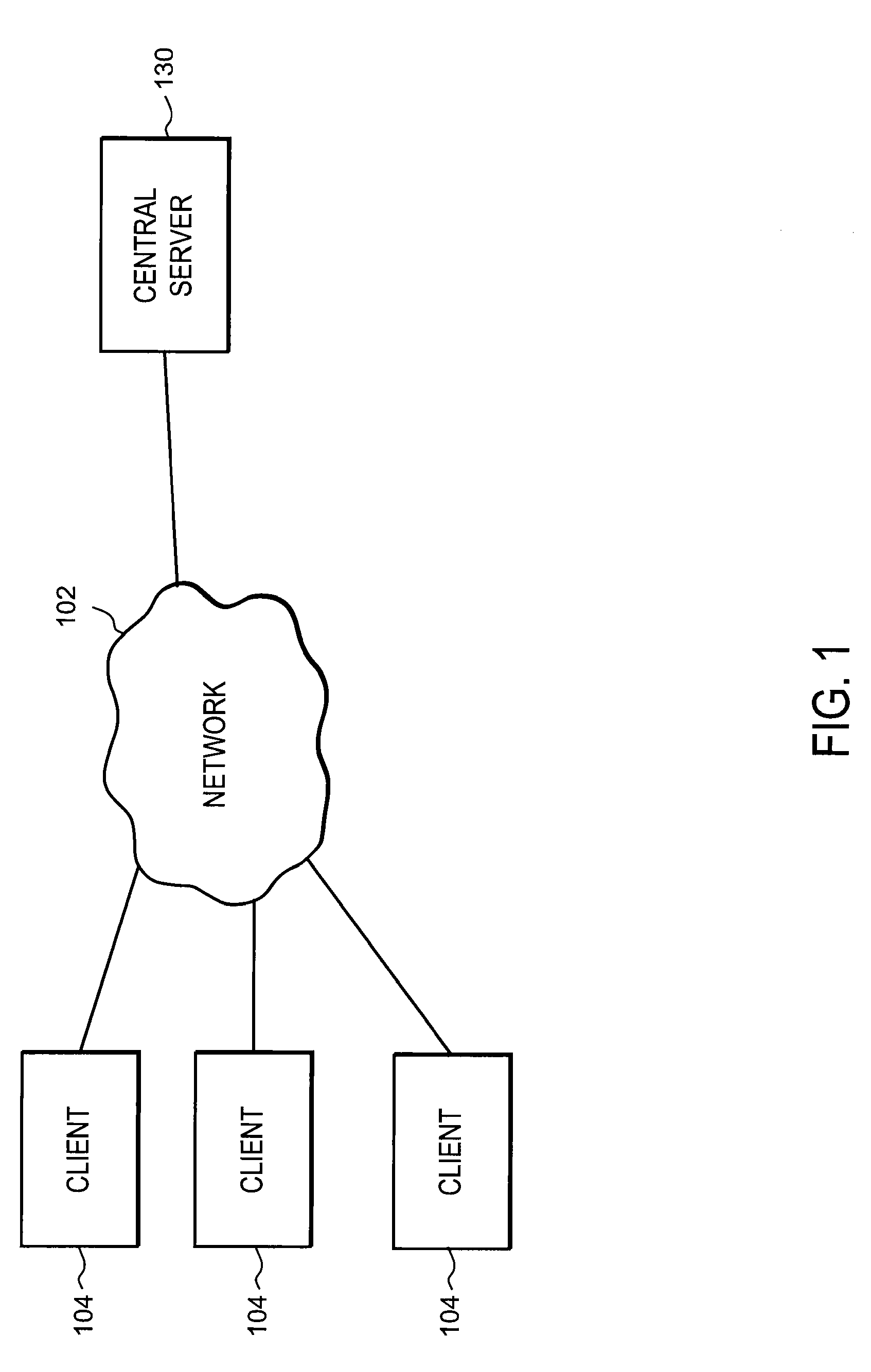
[0019]FIG. 1 is a high-level block diagram of a computing environment 100 according to one embodiment. The computing environment 100 comprises a central server 130 and clients 104 all connected by a network 102. Only three clients 104 are shown in FIG. 1 in order to simplify the description. Embodiments of the computing environment 100 can have many more clients 104 connected to the network 102.

[0020]In one embodiment, a cli...


PUM


Abstract

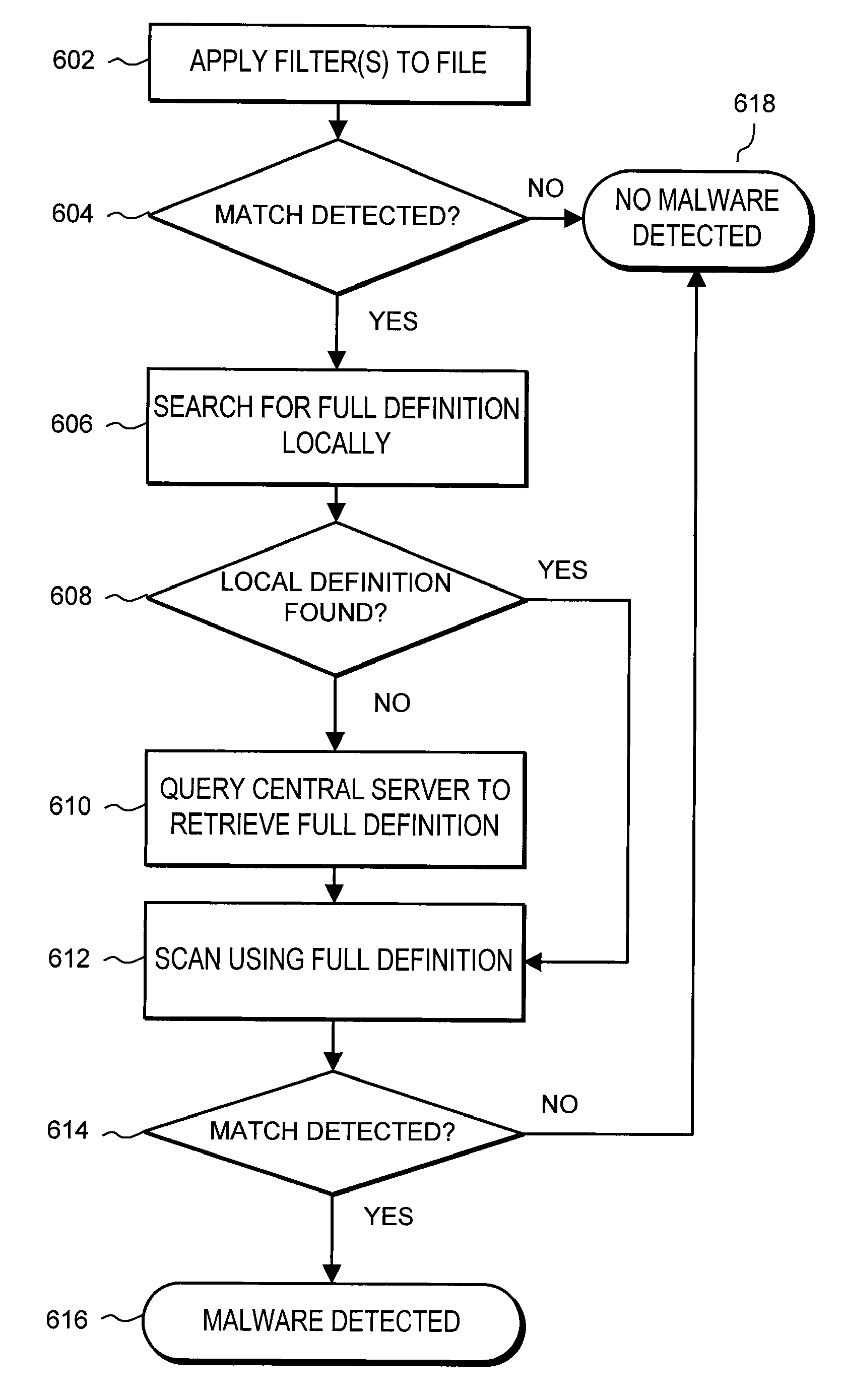
A system and method detects malware on client devices based on partially distributed malware definitions from a central server. A server stores malware definitions for known malware. The server generates one or more filters based on the malware definitions and distributes the filter(s) to client devices. The server also distributes full definitions to the clients for a subset of the most commonly detected malware. The client device scans files for malware by first applying the filter to a file. If the filter outputs a positive detection, the client scans the file using the full definition to determine if the file comprises malware. If the full definition is not stored locally by the client, the client queries the server for the definition and then continues the scanning process.

Description

BACKGROUND[0001]1. Field of Art[0002]The disclosure generally relates to computer security, and more specifically to detecting malware.[0003]2. Description of the Related Art[0004]Malware such as computer viruses, worms, Trojan horses, and spyware pose a constant threat to modern computer systems. In order to combat malicious files, computer systems typically run antivirus software that attempts to detect, identify, and remove the malicious files. Conventional antivirus software stores a database of definitions with each definition corresponding to known malware. The antivirus software periodically scans files on the client machine to detect malware matching the stored definitions. The detected malware can then be neutralized or eliminated.[0005]While anti-virus programs are able to detect and remove malware, new malware designed to work around existing programs is constantly being produced. Thus, it is important to frequently update these antivirus definitions so that newly release...

Claims


Application Information

Patent Timeline
Patent Type & Authority Patents(United States)
IPC IPC(8): H04L29/06
CPCG06F21/56H04L63/1416G06F21/564
Inventor SZOR, PETER
Owner CA TECH INC
Learn More