Systems and methods for monitoring groundwater, rock, and casing for production flow and leakage of hydrocarbon fluids

a technology of hydrocarbon fluid and monitoring system, which is applied in the direction of survey, borehole/well accessories, construction, etc., can solve the problems of limited access to these resources, contamination of groundwater, public exposure to natural gas and toxic chemicals, and considerable controversy surrounding natural gas extraction

Inactive Publication Date: 2012-07-10
AMERICAN PIONEER VENTURES
View PDF60 Cites 57 Cited by
  • Summary
  • Abstract
  • Description
  • Claims
  • Application Information

AI Technical Summary

Benefits of technology

[0018]Yet another embodiment of the present invention is a system for monitoring flow of hydrocarbon fluids in a horizontal lateral production casing of a shale gas formation, the system comprising a communication subsystem and a sensor subsystem embedded in the horizontal lateral production casing and connected to the communication subsystem, the sensor subsystem comprising at least two flow semiconductor sensors, each first flow sensor located between adjacent fracture clusters of said horizontal lateral, said first flow sensors adapted to measure relative flow between adjacent fracture clusters; and one or more processors for measuring temperature and flow data from the two flow sensors and providing said temperature and flow data to the communication subsystem for transmission to surface, wherein said flow sensors generate data on relative flow rates of hydrocarbons from each fracture cluster.

Problems solved by technology

The United States has vast resources of natural gas available for extraction, but until recent technological advances, the ability to access these resources was limited.
Furthermore, considerable controversy surrounds the environmental and health effects of natural gas extraction.
Gas drilling can potentially result in contamination of groundwater, air pollution, and public exposure to natural gas and toxic chemicals.

Method used


Image

  • Systems and methods for monitoring groundwater, rock, and casing for production flow and leakage of hydrocarbon fluids
  • Systems and methods for monitoring groundwater, rock, and casing for production flow and leakage of hydrocarbon fluids
  • Systems and methods for monitoring groundwater, rock, and casing for production flow and leakage of hydrocarbon fluids

Examples


Embodiment Construction

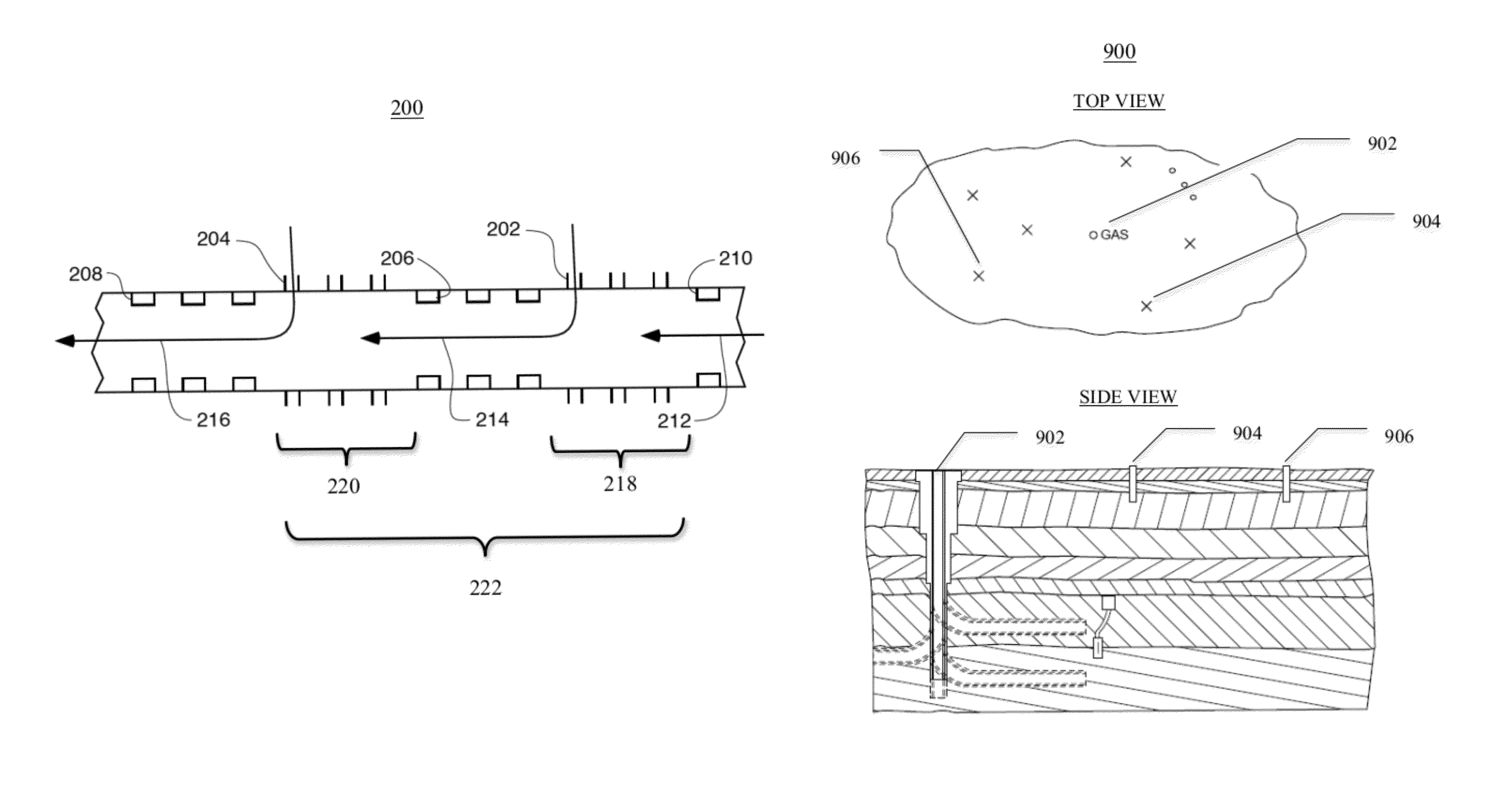
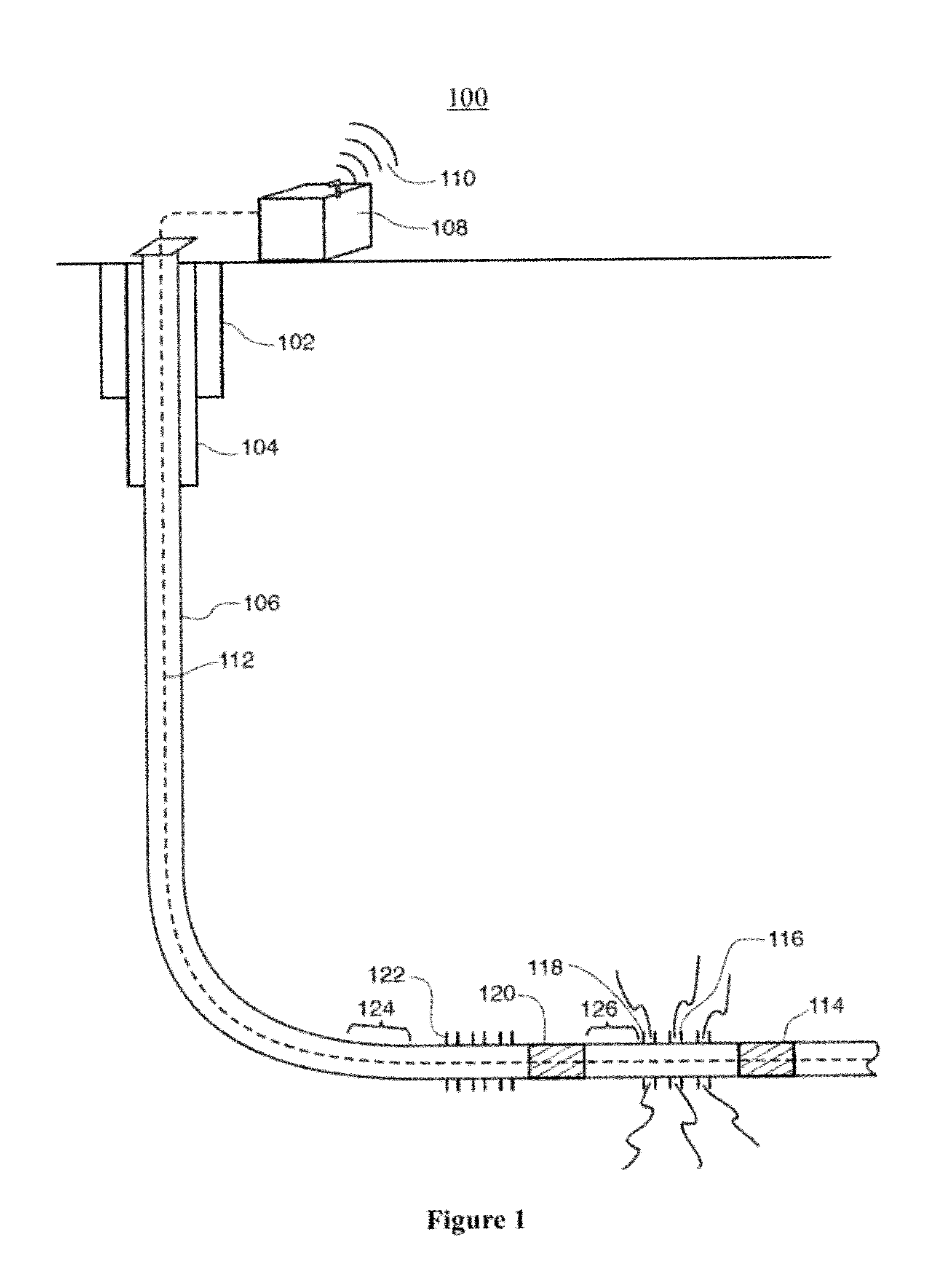
[0035]The system according to one embodiment of the present invention is composed of one or more subsystems, which can be practiced alone or in combination, which together allow for monitoring of groundwater, rock, and casing for production flow and leakage of hydrocarbon fluids. A flow measurement subsystem measures flow of hydrocarbons in the horizontal casing string. A well mechanical integrity monitoring subsystem monitors the mechanical integrity of the natural gas production well, including the junctures of a completed well. An aquifer monitoring subsystem directly monitors water aquifer(s) underneath and surrounding a natural gas production well or pad, including monitoring wells or existing water wells. A communication subsystem is used to communicate measurements taken downhole to the surface. The present system can be practiced with one or more of the disclosed subsystems. The rest of the disclosure describes each of these subsystems in detail.

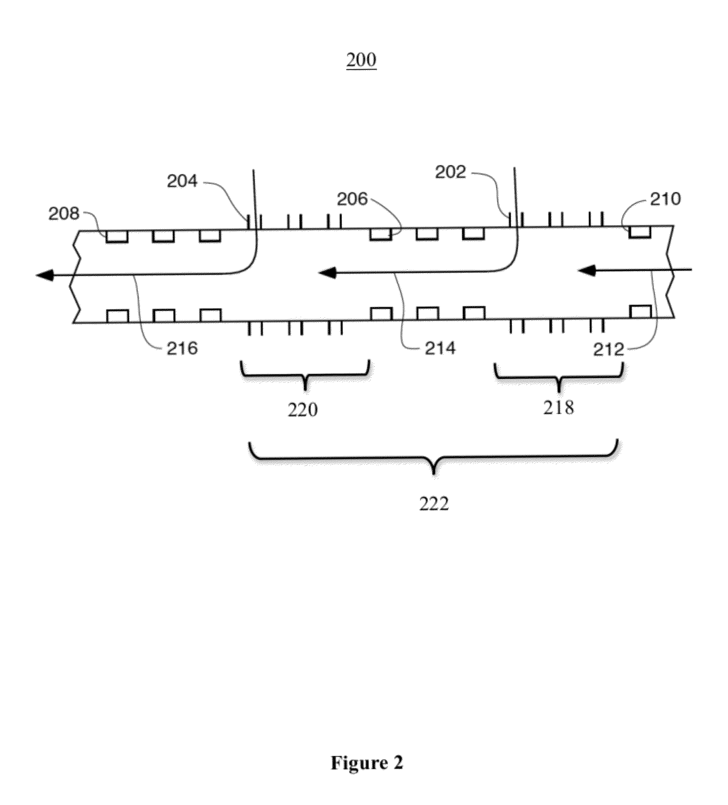
Flow Measurement Subsystem

[00...


PUM


Abstract

One embodiment of the present invention is a system comprising one or more subsystems, which can be practiced alone or in combination, which together allow for monitoring of groundwater, rock, and casing for production flow and leakage of hydrocarbon fluids. A flow measurement subsystem measures flow of hydrocarbons in the horizontal casing string. A well mechanical integrity monitoring subsystem monitors the mechanical integrity of the natural gas production well, including the junctures of a completed well. An aquifer monitoring subsystem directly monitors water aquifer(s) underneath and surrounding a natural gas production well or pad, including monitoring wells or existing water wells. A communication subsystem is used to communicate measurements taken downhole to the surface. The present invention may be used to enhance the production from a gas bearing shale formation, mitigate liability associated with hydrocarbon migration, and monitor for a loss of mechanical integrity of a well.

Description

FIELD OF THE INVENTION[0001]This invention relates to a monitoring system for shale gas wells to measure flow of hydrocarbon fluids, to detect a loss of mechanical integrity, and to identify and fingerprint a source of contamination associated with a leaking shale gas well. In addition to shale gas wells, the present invention may be applied to other types of natural gas wells as well as to oil wells.BACKGROUND OF THE INVENTION[0002]Natural gas is a vital component of the world's energy supply. It is a major source of electricity generation, is a relatively clean automobile fuel, and is used in residential homes for cooking, heating and cooling. Natural gas is a combustible mixture of hydrocarbon gases formed primarily of methane, which in its pure form is colorless and odorless. It is found in reservoirs underneath the earth, often associated with oil deposits. The United States has vast resources of natural gas available for extraction, but until recent technological advances, the...

Claims


Application Information

Patent Timeline
Patent Type & Authority Patents(United States)
IPC IPC(8): E21B47/06E21B47/10
CPCE21B43/14E21B47/065E21B47/10E21B47/07
Inventor HUSSAIN, DANIARMILLER, JAMES BROBERTS, JAY SCOTTCOOPER, JR., FRANK WILLIAMABBOTT, RYANCROCCO, LOUMALLIARIS, STEVEN G.
Owner AMERICAN PIONEER VENTURES
Why Eureka
Try Eureka