Steering unit for free flying, confined wing element

a free-flying, confined technology, applied in marine propulsion, special-purpose vessels, vessel construction, etc., can solve the problems of increasing the weight of the attachment means, controlling the flight and inefficient connection of the wing element to the ground attachment point via more than one tractive lin

Active Publication Date: 2012-07-10
SKYSAILS GMBH & CO KG
View PDF7 Cites 15 Cited by
  • Summary
  • Abstract
  • Description
  • Claims
  • Application Information

AI Technical Summary

Benefits of technology

[0041]Further, a number of tractive lifting force control lines are attached to the aerodynamic wing element along its widthwise central region. This improvement provides a reasonable reduction of the number of tractive lifting force control lines. It has been demonstrated that the central region of the aerodynamic wing element is most effective for controlling the lifting force, whereas the side regions have less influence on this. Thus, tractive lifting force control lines attached to the side regions may be omitted for ease of construction.
[0042]Still further, the additional moveable attachment means for con

Problems solved by technology

A general problem associated with such large scale wing elements is the control of their flight.
Moreover, since it is desired that the wing element flies at a high altitude in order to use the increased wind speed present there, it is not efficient to connect the wing element to the ground attachment point via more than one tractive line since this would increase the weight of the attachment means.
When selecting such an arrangement for the wind propulsion system, a first problem is the way of steering the direction and the speed of the wing element with the associated gondola.
A further problem

Method used


Image

  • Steering unit for free flying, confined wing element
  • Steering unit for free flying, confined wing element
  • Steering unit for free flying, confined wing element

Examples


Embodiment Construction

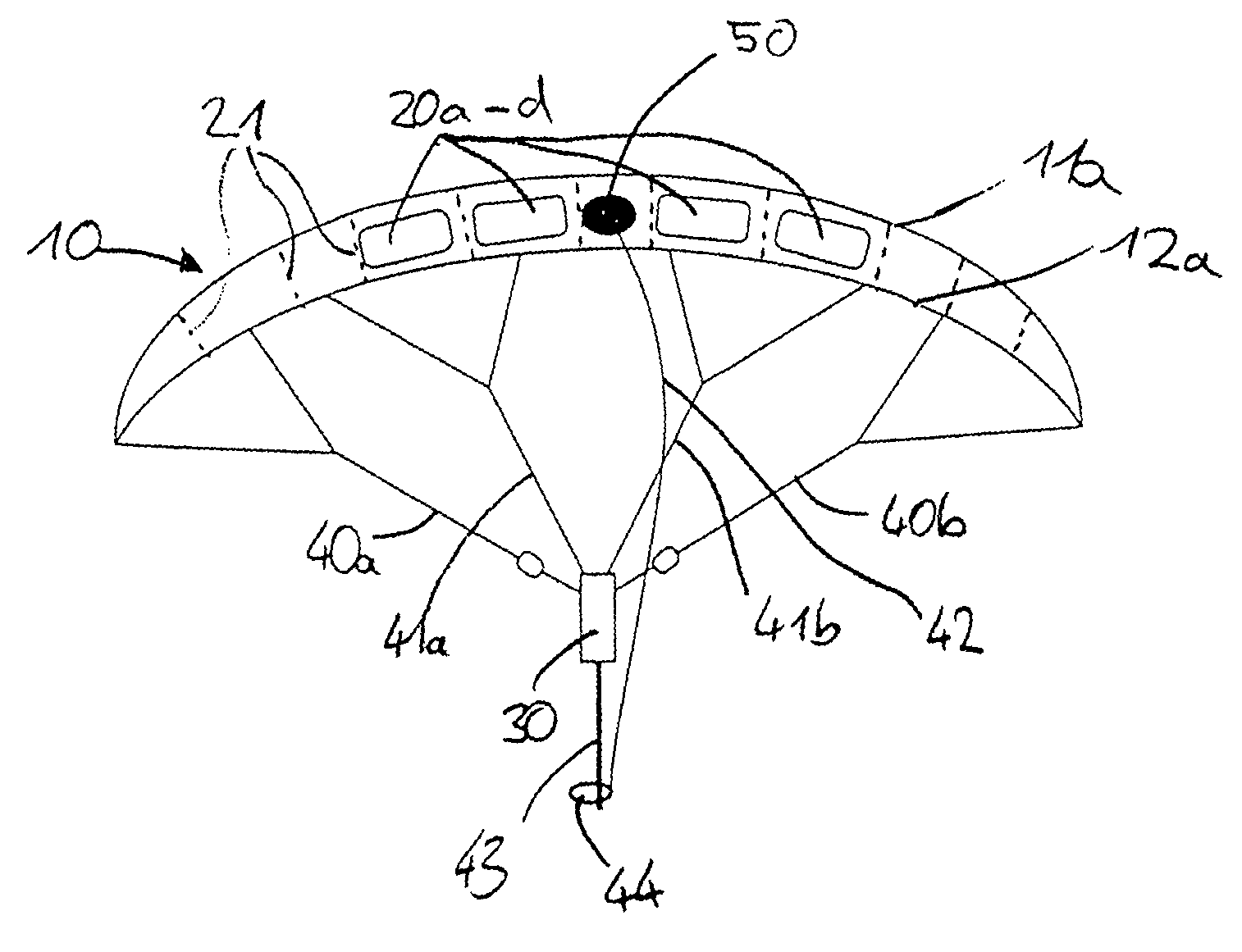
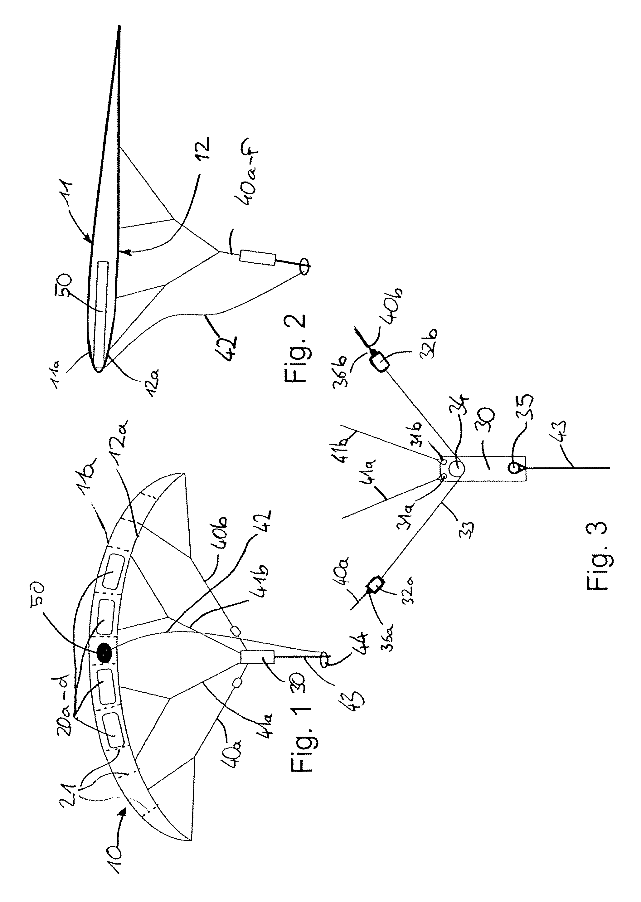
[0055]Referring to FIGS. 1 and 2 an aerodynamic wing element according to the invention may be shaped like a kite 10 comprising an upper layer 11 and a lower layer 12. In the frontal view according to FIG. 1 four openings 20a-d are visible in the leading edge 11a, 12a. These openings ventilate the inner space between the upper and lower layer 11, 12. The openings are arranged beside the horizontal longitudinal axis of the kite. In the lateral area between the leading edges 11a, 12a no openings are present.

[0056]The upper and lower layer are connected via a plurality of ribs 21 shown in dashed lines in FIG. 1. The assembly of upper layer, lower layer and the plurality of ribs provides a flexible wing element. This wing element is attached to a steering unit 30 via a plurality of tractive lines. Basically, starting from a large number of lines attached to the wing element these lines are merged to a reduced number of lines in a plurality of merging steps (for the sake of clarity only ...


PUM


Abstract

The invention relates to a steering unit for a wind propulsion system, the steering unit comprising a first fixed attachment means for securing a first end of a tractive cable the second end of which is secured to a device or a vehicle to which a tractive force shall be transferred, a second attachment means for attaching a number of tractive lines, the second end of which being secured to an aerodynamic wing element, a mechanical support frame connecting the first attachment means to the second attachment means for transferring a tractive force. The invention aims at providing such a steering unit with improved design for better maneuverability and stability. According to the invention the second attachment means of the improved steering unit comprise at least one upper fixed attachment point, a left moveable attachment point, a right moveable attachment point, and steering actuator means for varying the distance between the upper fixed attachment point and the left moveable attachment point and for varying the distance between the upper fixed attachment point and the right moveable attachment point.

Description

CROSS-REFERENCE TO RELATED APPLICATIONS[0001]This application is a National Stage of International Application No. PCT / EP2006 / 008959, filed Sep. 14, 2006, the disclosure of which is incorporated herein by reference.BACKGROUND AND SUMMARY[0002]The invention relates to a steering unit for a wind propulsion system, the steering unit comprising a first fixed attachment means for securing a first end of a tractive cable the second end of which is secured to a device or a vehicle to which a tractive force shall be transferred, a second attachment means for attaching a first end of a number of tractive lines, the second end of which being secured to an aerodynamic wing element. A mechanical support frame connects the first attachment means to the second attachment means to transfer a tractive force. A further aspect of the invention is an aerodynamic wind propulsion system comprising such a steering unit. Still further, the invention relates to a method of controlling such an aerodynamic w...

Claims


Application Information

Patent Timeline
IPC IPC(8): B64C31/06
CPCB63B35/7976B63B35/7979Y10S244/902B63H9/072B63H8/16B63B2035/009Y02T70/5236
Inventor WRAGE, STEPHANBRABECK, STEPHAN
Owner SKYSAILS GMBH & CO KG
Why Eureka
Try Eureka