Rotor hub, motor, and disk driving device

a technology of rotating hubs and drives, applied in the direction of instruments, record information storage, etc., can solve the problems of difficult to further minimize the heat deformation occurring after the connection cannot be minimized, and the error in reading and/or writing information on the disk, etc., to achieve the effect of minimizing the deformation of the disk loading portion

Inactive Publication Date: 2012-07-17
NIDEC CORP
View PDF27 Cites 8 Cited by
  • Summary
  • Abstract
  • Description
  • Claims
  • Application Information

AI Technical Summary

Benefits of technology

[0011]In view of the problems described above, preferred embodiments of the present invention provide a disk driving device arranged to minimize a deformation of the disk loading portion due to the force generated by the yoke.
[0014]According to various preferred embodiments, the deformation of the disk loading portion due to the force from the yoke is minimized.

Problems solved by technology

When the disk loading portion is deformed, the disk may be rotated with a runout which can cause an error in reading and / or in writing of information on the disk.
Despite these conventional techniques, however, although a heat deformation of the disk loading portion can be minimized to a certain extent, it is very difficult to further minimize the deformation of the disk loading portion because a connecting portion between the yoke and the hub is near the disk loading portion and, therefore, a force generated by the yoke is easily conducted to the disk loading portion.
However, the heat deformation occurring after the connection is made cannot be minimized.

Method used


Image

  • Rotor hub, motor, and disk driving device
  • Rotor hub, motor, and disk driving device
  • Rotor hub, motor, and disk driving device

Examples


Embodiment Construction

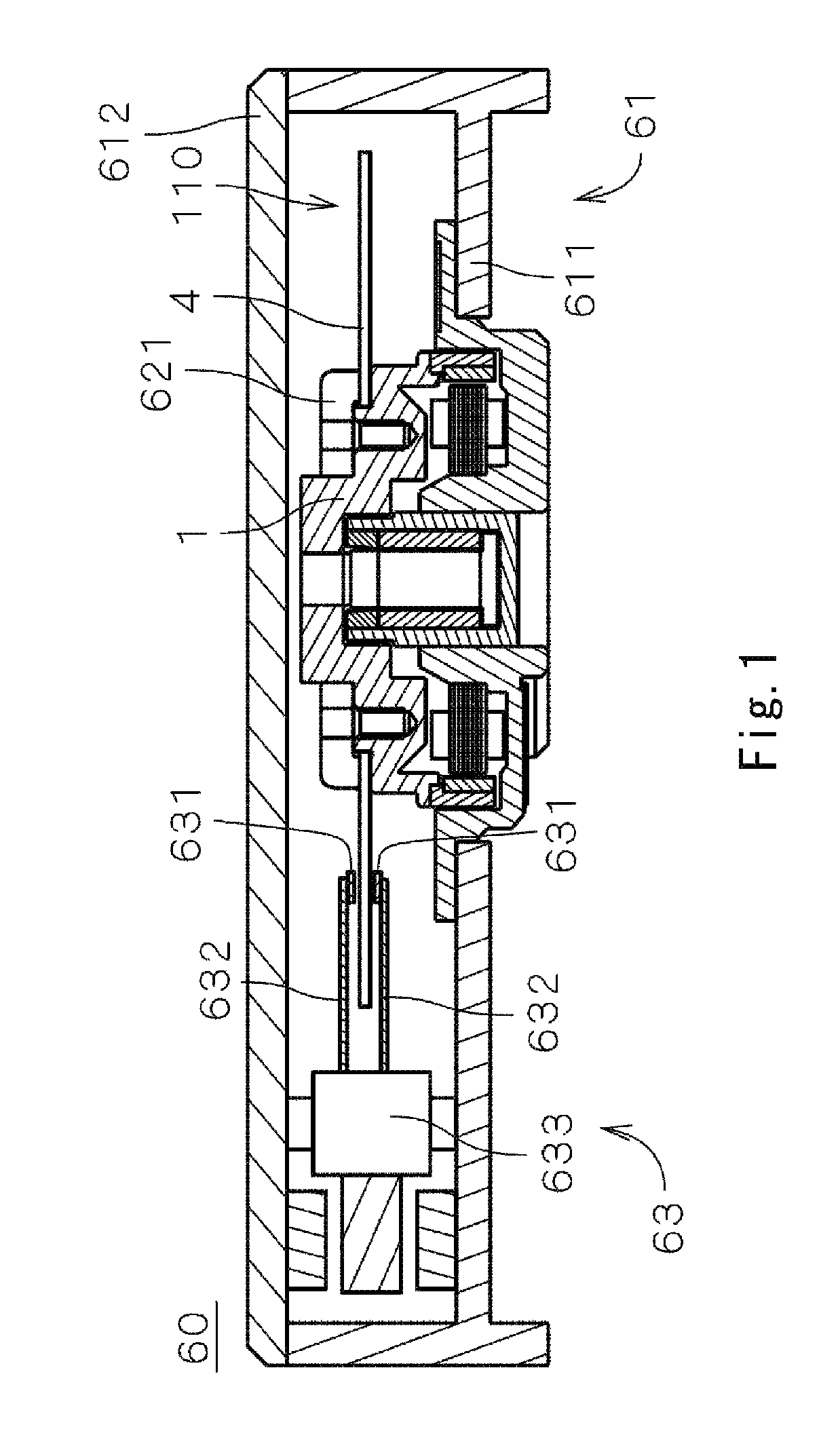
[0030]FIG. 1 is a diagram showing an internal configuration of a disk driving device 60 including an electric spindle motor 1 (hereinafter, referred to as “motor 1”) according to a first preferred embodiment of the present invention. The disk driving device 60 is a hard disk device which includes a shaft connecting portion connected to a shaft serving as a central axis; a disk 4 having a circular shape, an access portion 63 for reading and / or writing on the disk 4; the electric motor 1 for retaining and rotating the disk 4; and a housing 61 having an internal space 110 for accommodating therein the disk 4, the access portion 63, and the motor 1.

[0031]As shown in FIG. 1, the housing 61 includes a first housing member 611 having an opening at a top portion thereof for accommodating therein the motor 1 and the access portion 63, and a plate shaped second housing member 612 defining the internal space 110 by covering the opening of the first housing member 611. In the disk driving devic...


PUM

PropertyMeasurementUnit
depthaaaaaaaaaa
depthaaaaaaaaaa
depthaaaaaaaaaa

Abstract

A rotor hub includes a shaft connecting portion arranged to be connected to a shaft serving as a central axis, a disk loading portion centered about the central axis and arranged to support a disk shaped storage medium mounted thereon, a yoke arranged below the disk loading portion and supporting a field magnet at one of an inner side surface thereof and an outer side surface thereof, and a flexible portion connecting the disk loading portion to the yoke and being flexible with respect to a force applied thereto from the yoke.

Description

BACKGROUND OF THE INVENTION[0001]1. Field of the Invention[0002]The present invention relates to a rotor hub to which a disk is attached, a motor having the rotor hub, and a disk driving device having the motor.[0003]2. Description of the Related Art[0004]Conventionally, a disk driving device such as a hard disk drive includes a spindle motor (hereinafter, referred to as a “motor”) for driving a storage medium disk attached to a rotor hub. The rotor hub is usually made of a metal material such as aluminum or aluminum alloy. The disk is affixed to the rotor hub via a clamper or the like while the bottom surface of the disk is in contact with the rotor hub.[0005]In the motor such as one described above, a field magnet and a yoke which prevents a loss of a magnetomotive force by covering outer and inner sides of the field magnet are arranged below a disk loading portion. The field magnet generates a torque between an armature and the field magnet. The yoke is made of a ferromagnetic ma...

Claims


Application Information

Patent Timeline
Patent Type & Authority Patents(United States)
IPC IPC(8): G11B17/02
CPCG11B19/2045G11B17/0282
Inventor IGUCHI, TAKUROSAMESHIMA, YOSHIHIROTAMAOKA, TAKEHITOSUGIURA, RYOUJI
Owner NIDEC CORP
Why Eureka
Try Eureka