Suppression of parasitic lasing

a parasitic lasing and laser technology, applied in the direction of laser details, active medium materials, electrical equipment, etc., can solve the problems of high cost, bulky, heavy, current fielded laser range finders and laser designators, etc., to reduce the overall fabrication cost of laser cavities, simplify the production of laser range finders, and the inventive method is simpl

Inactive Publication Date: 2012-07-17
UNITED STATES OF AMERICA THE AS REPRESENTED BY THE SEC OF THE ARMY
View PDF4 Cites 0 Cited by
  • Summary
  • Abstract
  • Description
  • Claims
  • Application Information

AI Technical Summary

Benefits of technology

[0009]Size, weight, performance and production costs are parameters that benefit by this invention. The invention simplifies the producibility of a laser range finder or laser designator system. The fabrication of the laser gain medium crystals using the inventive method can be done using batch processing. Large rectangular, laser optical components can be polished and properly coated. This batch process can greatly reduce the overall fabrication costs of the laser cavity. The inventive method is very simple. It can reduce the cost of processing the laser gain medium crystals by not requiring a fine polish and then having to try to suppress the parasitic lasing by adding additional cladding or labor intensive and expensive coatings.
[0010]The present invention may be used as the laser gain medium in very compact laser range finders and laser designators. The design of the inventive method also lends itself to placement in other laser-based devices. These may be medical devices, industrial tools or scientific equipment that would benefit from the size / weight reduction, dependable performance, and low cost of the inventive method.

Problems solved by technology

Unfortunately, current fielded laser range finders and laser designators are bulky, heavy and expensive.

Method used


Image

  • Suppression of parasitic lasing
  • Suppression of parasitic lasing

Examples


Embodiment Construction

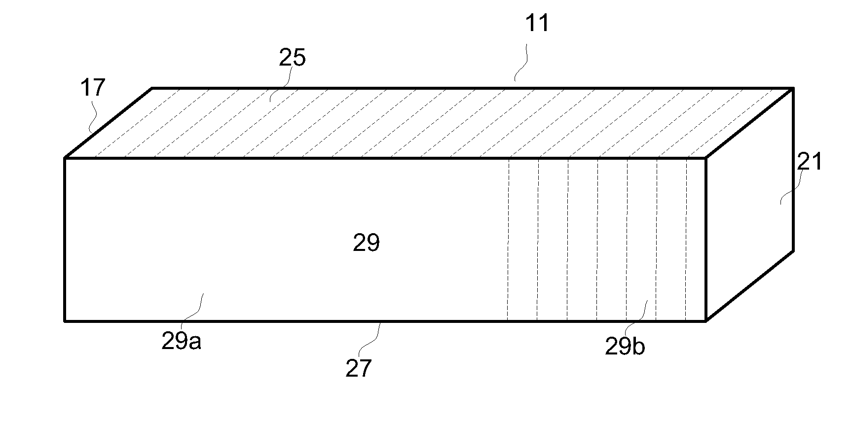
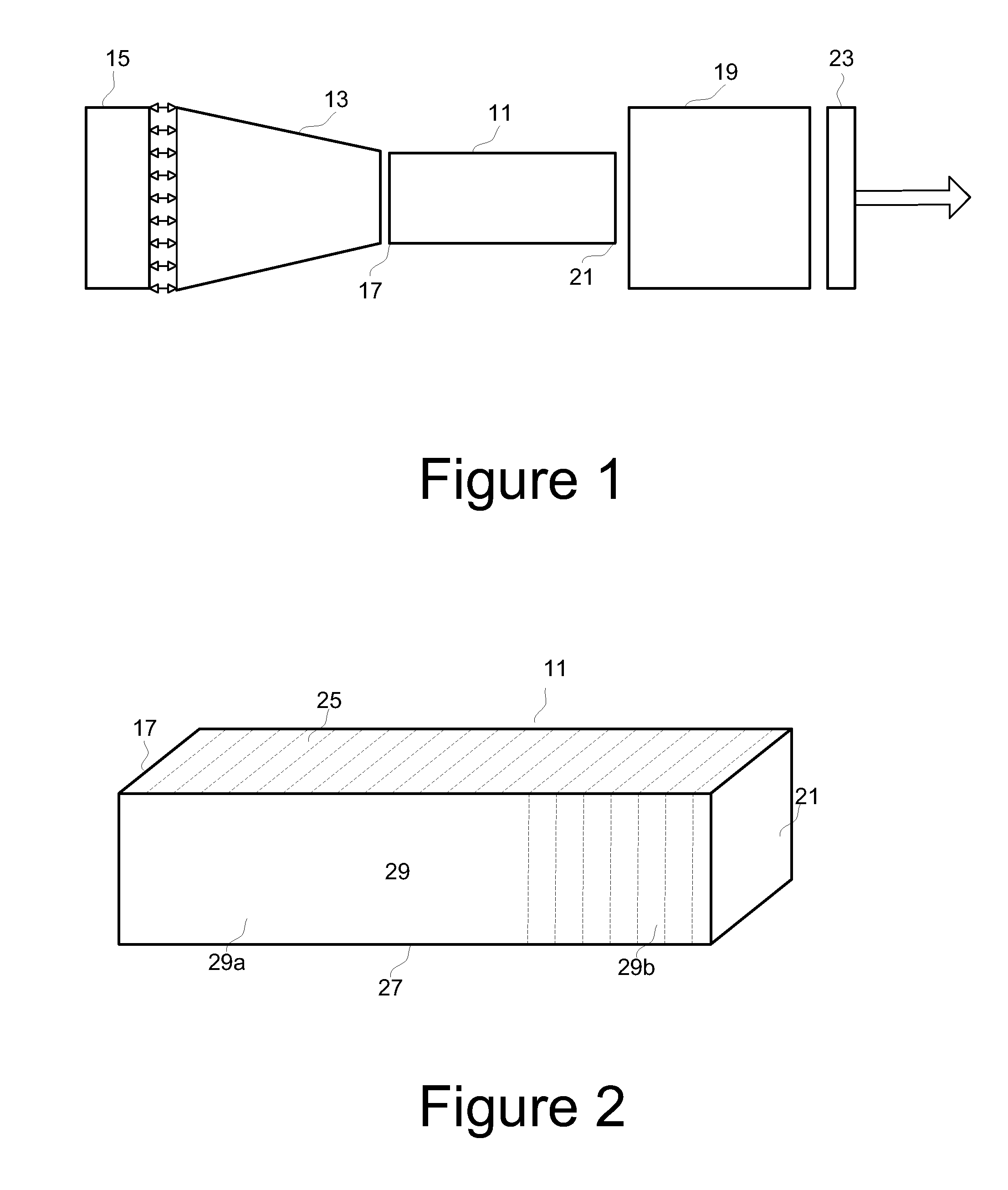
[0014]FIG. 1 shows an exemplary embodiment of a total internal reflecting laser cavity. The laser cavity consists of several optical components fused into one “block” or pseudo-monolithic laser cavity. It is termed “pseudo-monolithic” because many components are incorporated into the structure. It is called “a total internal reflecting cavity” because its design is intended for laser diode pumping from the end and the laser cavity directs all the pumping radiation into the laser gain medium. Referring to FIG. 1, the laser cavity includes a gain medium crystal 11, a total internal reflecting concentrator block 13 whose input end is sized to fit an external spatially extended stack of diode laser bars 15, and whose output end is fused to the input face 17 of the gain medium crystal 11, a Q-switch 19 fused to the output face 21 of the gain medium crystal 11, and an output coupler 23 fused to the Q-switch 19. The gain medium may be Nd:YAG, Nd:YLF, or Nd:YVO4, for example. The input face...


PUM

PropertyMeasurementUnit
Sizeaaaaaaaaaa
weightaaaaaaaaaa
size/weightaaaaaaaaaa

Abstract

A laser gain medium crystal comprising a square rod of laser gain medium material having top and bottom surfaces that are finely ground to introduce scattering surfaces to cancel parasitic lasing. The square rod of laser gain material has input and output faces and side surfaces, and portions of the side surfaces near the output face of the square rod are finely ground to introduce scattering surfaces to cancel parasitic lasing. The rest of the side surfaces of the square rod are polished.

Description

GOVERNMENT INTEREST[0001]The invention described herein may be manufactured, used, sold, imported, and / or licensed by or for the Government of the United States of America.FIELD OF THE INVENTION[0002]This invention relates in general to solid state lasers and more particularly, to diode-pumped solid state lasers.BACKGROUND OF THE INVENTION[0003]Laser range finders and laser designators are becoming an increasingly vital component in high precision targeting engagements. The precise and accurate range to target information is an essential variable provided by laser range finders to precisely designate a target.[0004]Unfortunately, current fielded laser range finders and laser designators are bulky, heavy and expensive. These laser range finders and laser designators were not developed with the individual user in mind.[0005]It is therefore an object of this disclosure to make the development and fabrication of a very compact laser range finder or laser designator possible.SUMMARY OF T...

Claims


Application Information

Patent Timeline
Patent Type & Authority Patents(United States)
IPC IPC(8): H01S3/11
CPCH01S3/0627H01S3/0606H01S3/0625H01S3/094057H01S3/09408H01S3/09415H01S3/11H01S3/1611H01S3/1653H01S2301/02H01S3/1123
Inventor NETTLETON, JOHN E.BARR, DALLAS N.
Owner UNITED STATES OF AMERICA THE AS REPRESENTED BY THE SEC OF THE ARMY
Why Eureka
Try Eureka