Electromagnetic actuating apparatus

a technology of actuating apparatus and actuating device, which is applied in the direction of non-mechanical valves, magnetic bodies, valve drives, etc., can solve the problems of complex realisation of multiple tappet technology and difficulty in exact assignment during assembly, and achieve the effect of high operational reliability, beneficial maintenance and mounting properties

Active Publication Date: 2017-01-24
ETO MAGNETIC GMBH
View PDF9 Cites 0 Cited by
  • Summary
  • Abstract
  • Description
  • Claims
  • Application Information

AI Technical Summary

Benefits of technology

[0011]According to a preferred development of the invention, in turn in a fundamentally structural deviation from the geometric realisation principle of the technology forming the generic type according to WO 2010 / 063394, it is provided and advantageous, to construct the coil unit realised as a single coil surrounding an axially and centrally extending section of the core unit. If this arrangement is surrounded by a suitable approximately cupular or hollow cylindrical housing, a compact unit, which is simple to produce and magnetically powerful, is therefore created, wherein preferably and in turn according to a development the (identically poled) end face protrudes axially out of a surrounded or overlap area of the coil. In turn, alternatively or additionally, it is provided in the context of a preferred development to close one (such) housing at the end side by means of a guide element (guide section), which can then advantageously on the one hand offer guides for the plurality of tappet units (wherein the tappet units can then emerge by means of a respective end-side engagement section), on the other hand such a guide section, as part of a magnetic circuit closed for example by the housing, internally not only offers a stop for the permanent magnet means of the respective tappet units, but also can realise a bistability for the de-energised case, by means of a suitable permanent magnetic adhesive action.
[0012]In the preferred constructive-geometric configuration of the core unit, it is on the one hand provided according to a development and preferably to construct the core unit as an individual, further preferably integrally realised core element. This can then engage by means of the previously described axial central section into the (surrounded) coil and at the same time have a section extending out of the coil and radially expanding, which section then realises the identically poled end face of the core unit at the end or front side. A configuration of the invention of this type in turn connects constructive simplicity and therefore simple producibility and mountability with beneficial electromagnetic or flux-guiding properties, so that for both operating states—in the de-energised adhesive state of the tappet units and in the moving or extended state of the tappet units—optimised flux conditions are present in each case.
[0018]As a result, the present invention is therefore exceptionally suitable for realising a camshaft adjustment using a plurality of suitably engaging tappet units, wherein the present invention combines constructive simplicity and high operational reliability with beneficial maintenance and mounting properties, particularly the opportunity presents itself that with substantially standardised components, synchronous and parallel movable tappet movements can be realised.

Problems solved by technology

Accordingly, realisation of a multiple tappet technology is complex and furthermore entails difficulties in exact assignment during assembly.

Method used


Image

  • Electromagnetic actuating apparatus
  • Electromagnetic actuating apparatus
  • Electromagnetic actuating apparatus

Examples


first embodiment

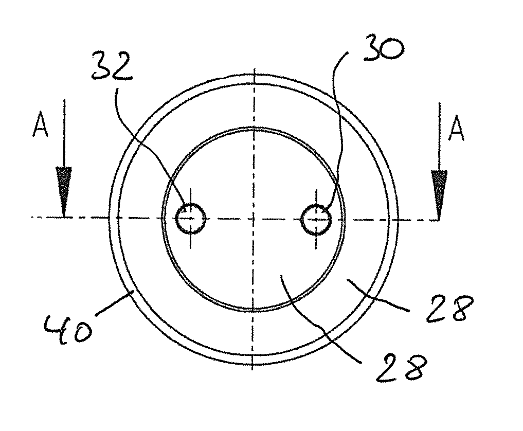
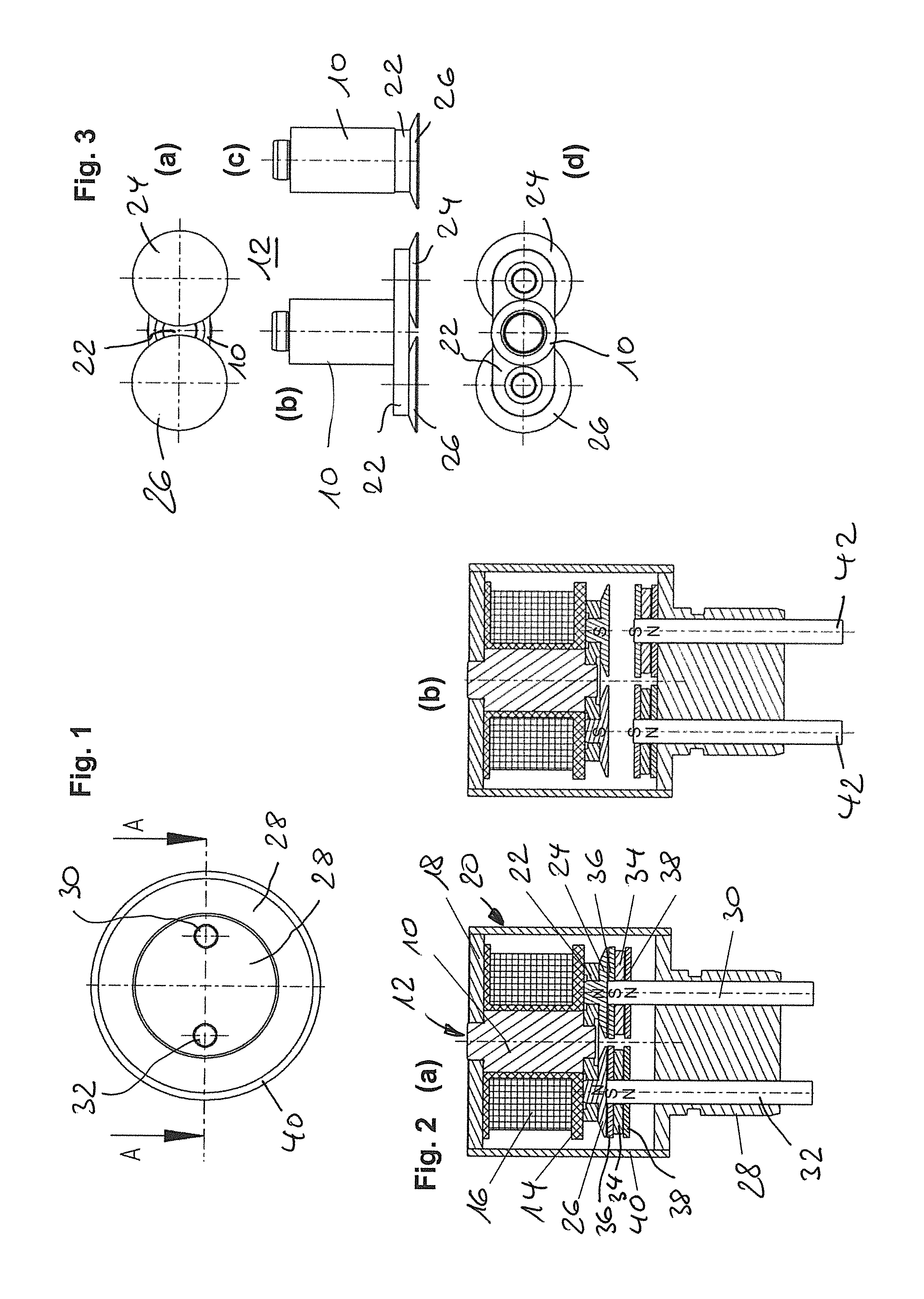
[0026]A cylindrical core element 10 of the core unit 12, which is constructed in multiple pieces and illustrated in detail in FIG. 3, is surrounded on the shell side by a coil 16 wound on a coil carrier 14 and engages at one end into a disc-shaped base section 18 of a housing 20 of the actuating device of the first embodiment shown in FIGS. 1 to 3.

[0027]At the end of the core element 10 axially opposite the housing base 18, the same is magnetically conductively connected to a connecting or bridge piece 22 extending transversely to the axial direction (vertical direction in the figure illustration of FIG. 2), into which plate-shaped (FIG. 3) core end pieces 24, 26 magnetically conductively engage as a pair.

[0028]At the end, these form an end face of the core unit 12 essentially lying in a common plane running transversely to the longitudinal axis.

[0029]The first exemplary embodiment shown in FIGS. 1 to 3 realises an electromagnetic actuator device with a plurality of tappet units 30,...

second exemplary embodiment

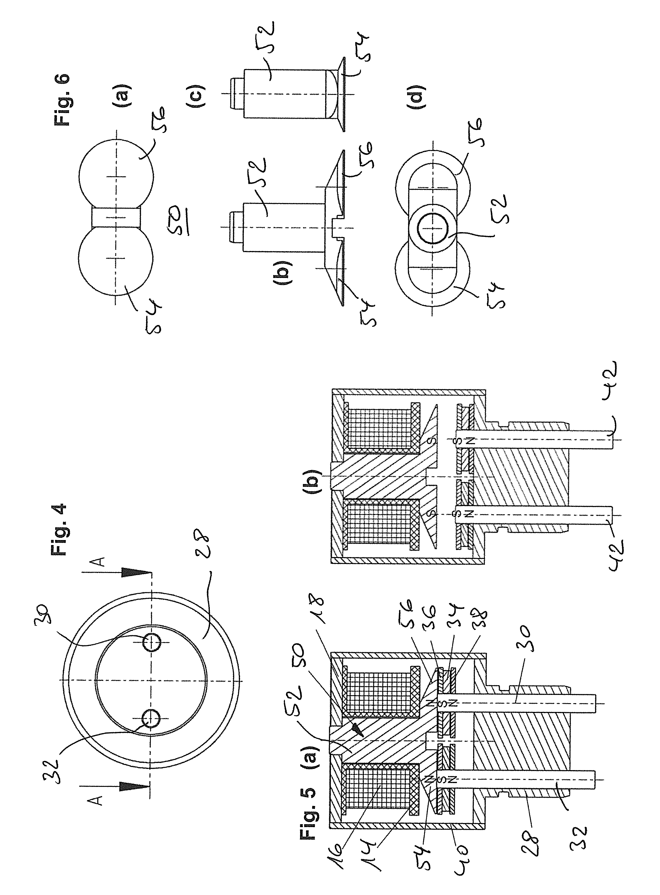
[0034]FIGS. 4 to 6 describes an alternative configuration of the core unit, in an otherwise identical constructive realisation of the electromagnetic actuating device. In the constructive details of the second exemplary embodiment according to FIG. 4 to FIG. 6, in comparison with the first exemplary embodiment (FIGS. 1 to 3), identical reference numbers show identical or equivalent modules, so that only a description of the differently realised core unit takes place for the further description.

[0035]As can be seen from the sectional views of FIGS. 5 (a) or (b) in particular, the core unit 50 is constructed in one piece in FIG. 1. According to the module 10 of the first exemplary embodiment, this one-piece core unit contains a central section 52, which is adjoined by a pair of radially widened core sections 54, which, in turn provided with a conical shape 56, construct an identically poled surface for interaction with the tappet units 30, 32 or the permanent magnet modules 34, 36, 38...


PUM

PropertyMeasurementUnit
permanent magnetisationaaaaaaaaaa
permanent magnetizationaaaaaaaaaa
areaaaaaaaaaaa

Abstract

An electromagnetic actuator device having a core unit (12;50) having a coil means (16), which core unit is constructed for interacting with armature means (34,36,38,32,30) that are movably guided relatively to the core unit, as a reaction to an energizing of the coil means, wherein the armature means have a plurality of tappet units (30, 32), which are spatially spaced from one another and can be driven simultaneously, to which tappet units, permanent magnet means (34) are assigned in the direction towards the core unit, which permanent magnet means have a permanent magnetization along a respective movement longitudinal axis of the tappet units, wherein the plurality of tappet units that can be driven parallel to one another magnetically interacts with an identically poled end face of the core unit and the permanent magnet means have an axially identically directed permanent magnetization.

Description

BACKGROUND OF THE INVENTION[0001]The present invention relates to an electromagnetic actuation device according to the preamble of the main claim. A device of this type is known from the applicant's WO 2010 / 063394 A1 and describes a core unit having a coil means, which core unit is constructed for interacting with armature means that are movably guided relatively to the core unit, as a reaction to an energising of the coil means. The armature means have a plurality of tappet units, which in each case have permanent magnet means at the end thereof that are directed towards the core unit. As a reaction to the energising of the core unit and the polarity chosen for this energising, the possibility therefore arises to selectively drive individual tappet units, in that the core unit repels a respective one of the permanent magnet units by means of the electromagnetically generated flux. Thus, depending on the configuration of the device, a contra-rotating movement of a pair of tappet uni...

Claims


Application Information

Patent Timeline
Patent Type & Authority Patents(United States)
IPC IPC(8): F01L9/04H01F7/16F01L13/00F01L1/34F01L25/08H01F7/08
CPCF01L25/08F01L1/34F01L13/0036H01F7/1646F01L2013/0052H01F7/081H01F2007/1669
Inventor RIGLING, TIMO
Owner ETO MAGNETIC GMBH
Why Eureka
Try Eureka