
Viewing device for aircraft comprising means of displaying the final destination and associated display method

a viewing device and aircraft technology, applied in the field of synthetic vision systems, can solve the problems of catastrophic civilian airplane accidents and the inability to identify this area, and achieve the effect of reducing the number of aircra

Active Publication Date: 2012-07-17
THALES SA
View PDF11 Cites 12 Cited by
  • Summary
  • Abstract
  • Description
  • Claims
  • Application Information

AI Technical Summary

Benefits of technology

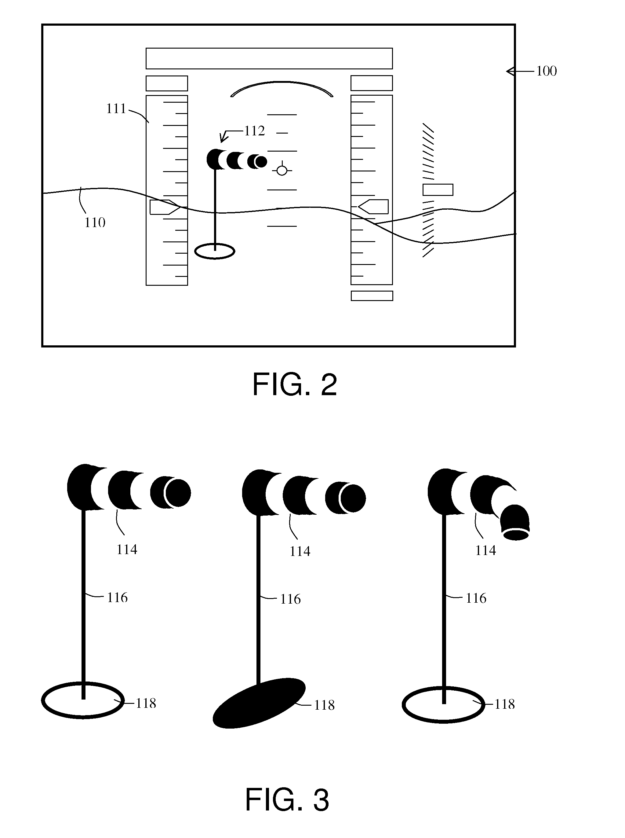
This solution reduces pilot workload and stress by providing a clear, intuitive representation of the final destination and its environment, including critical landing data like wind direction and terrain inclination, enhancing the pilot's ability to navigate and identify the landing area effectively.

Problems solved by technology

CFITs are the leading cause of catastrophic civilian airplane accidents.
At low overflight altitude, it is therefore almost impossible to identify this area.

Method used


Image

  • Viewing device for aircraft comprising means of displaying the final destination and associated display method
  • Viewing device for aircraft comprising means of displaying the final destination and associated display method
  • Viewing device for aircraft comprising means of displaying the final destination and associated display method

Examples


Embodiment Construction

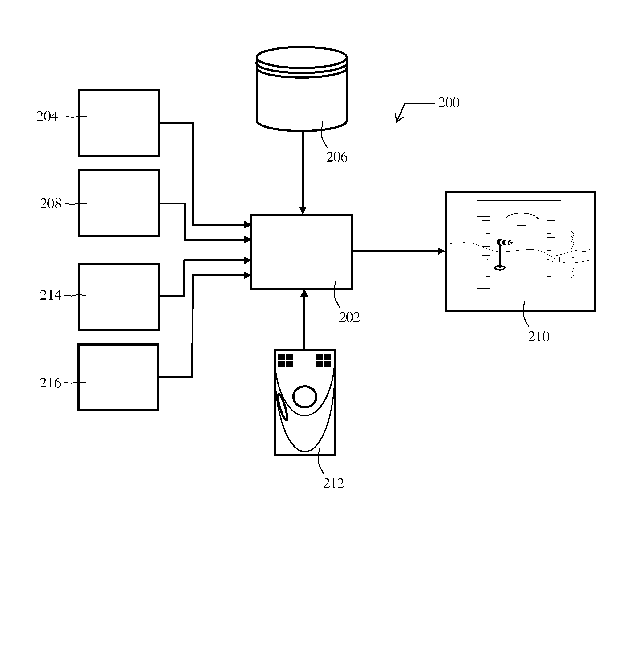
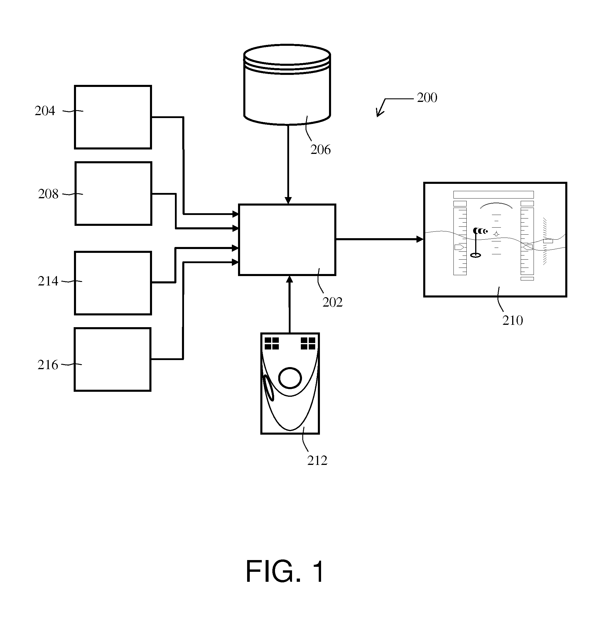
[0024]As an example, FIG. 1 represents one possible embodiment of a system according to the invention for aeronautical applications. The graphical display system 200 is installed in an aircraft and comprises a computer or a processor 202 configured to provide a viewing screen 210 with the information to be displayed.

[0025]One or more data sources are linked to the processor 202. These data sources include a cartographic database or information regarding the terrain 206 used to plot the perspective view. These databases are generally positioned in the aircraft. The data can also originate from the ground via transmission means or “data links”. Furthermore, these data can be stored on different peripheral devices such as diskettes, hard disks, CD-ROMs, volatile memories, non-volatile memories, RAMs or any other means that can be used to store data.

[0026]The system comprises an input system called “DIRECT TO”204 which can be a “GPS” system, GPS being an acronym standing for Global Posi...


PUM


Abstract

The general field of the invention is that of synthetic vision system SVS type viewing systems, for aircraft, said system comprising at least one navigation database, a cartographic database of a terrain, position sensors, anemometric sensors, sensors for measuring the gradient of said terrain, an electronic computer, a man-machine interface means and a display screen, the computer comprising means of processing the various information obtained from the databases, from the sensors and from the interface means, said processing means arranged so as to provide on the display screen a synthetic image of the terrain comprising a representation of the final destination in the form of an air sock of aeronautical type.

Description

RELATED APPLICATIONS[0001]The present application is based on, and claims priority from, French Application Number 08 04888, filed Sep. 5, 2008, the disclosure of which is hereby incorporated by reference herein in its entirety.BACKGROUND OF THE INVENTION[0002]1. Field of the Invention[0003]The general technical field of the invention is that of synthetic vision systems, known by the acronym SVS, used more particularly in aeronautics to present piloting or navigation information to the pilot in the most ergonomic possible way. In the present case, the graphic representation concerns the display of the final destination.[0004]2. Description of the Prior Art[0005]The SVS-type display devices provide the pilot with a better awareness of the surrounding hazards such as collisions with the ground with no loss of control, commonly called CFIT which stands for “Controlled Flight Into Terrain”. CFITs are the leading cause of catastrophic civilian airplane accidents. The aeronautical industr...

Claims


Application Information

Patent Timeline
Patent Type & Authority Patents(United States)
IPC IPC(8): G06F19/00
CPCG01C21/00G01C23/00G08G5/0021
Inventor BACABARA, CORINNENOUVEL, CHRISTIANPERBET, JEAN-NOEL
Owner THALES SA
Learn More