Armrest

a technology for armrests and supports, applied in the field of armrests, can solve the problems of complicated assemblage, complicated structure, time-consuming, etc., and achieve the effects of saving labor, time, cost, material and resources, and avoiding complicated assemblag

Active Publication Date: 2012-07-24
FANG TIEN CHING
View PDF6 Cites 10 Cited by
  • Summary
  • Abstract
  • Description
  • Claims
  • Application Information

AI Technical Summary

Benefits of technology

[0012]Preferably, the body further includes a second slider formed on the upper portion of the body and spaced from the first slider. A gap is formed between the first and second sliders. The gap forms a thin portion in the body. The thin portion of the body has a thickness allowing the body to flex. The second slider includes two arms slideably abutting the lateral walls of the guiding groove, allowing relative sliding movement between the second slider and the armrest base along the guiding groove.
[0013]The armrest base and the support of the armrest according to the present invention can be assembled with a simple mechanism, avoiding complicated assemblage. Thus, labor, time, costs, material, and resources are saved. The wastes to be treated are lesser than conventional armrests when the armrest according to the present invention is discarded.

Problems solved by technology

Conventionally, assemblage of the armrest base and the support requires complicated structure.
The structure can be more complicated if additional functions, such as rectilinear adjustment of relative position between the armrest base and the support, are required.
The assemblage is more complicated and time-consuming, increasing the costs.

Method used


Image

  • Armrest
  • Armrest
  • Armrest

Examples


Embodiment Construction

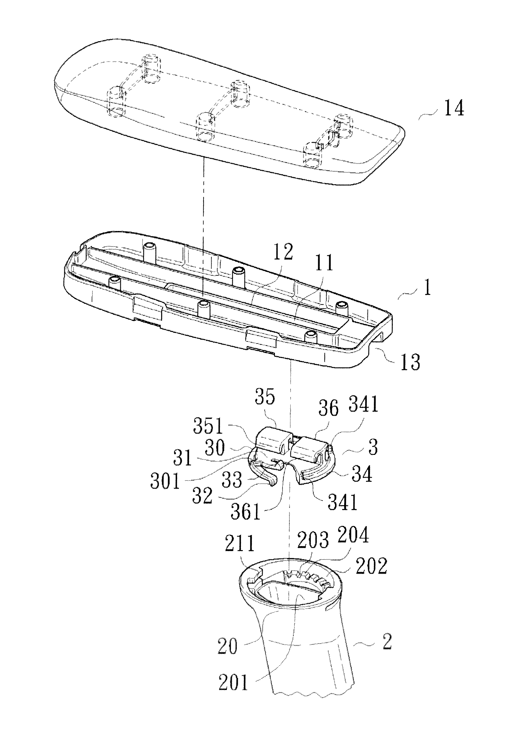
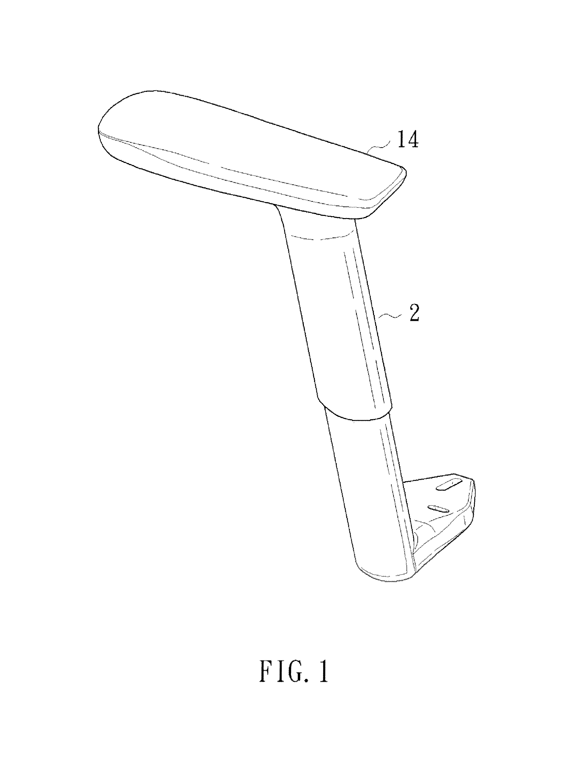
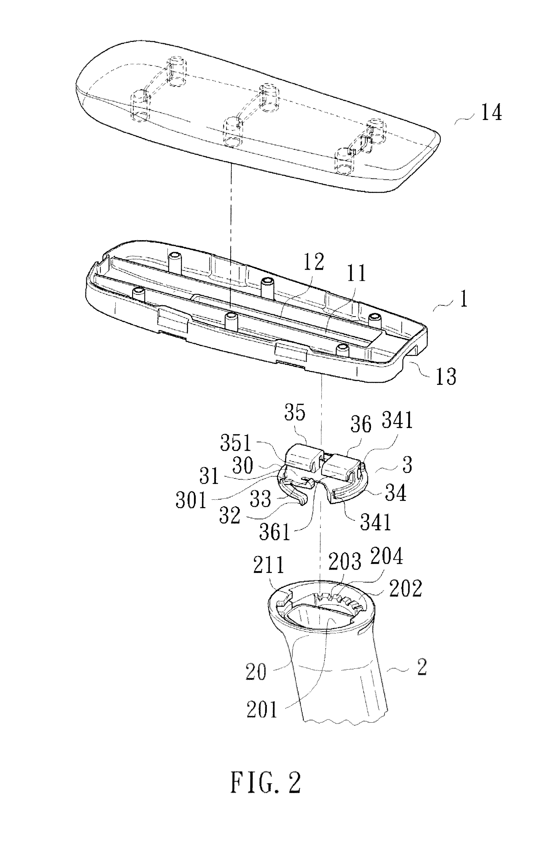
[0022]With reference to FIGS. 1 and 2, an armrest according to the present invention includes an armrest base 1, a support 2, and an engaging member 3. The armrest base 1 includes a guiding groove 11 having two lateral walls 12. An opening 13 is formed in a rear end of the armrest base 1 and in communication with the guiding groove 11. A pad 14 can be mounted on top of the armrest 1, allowing a user to place his or her elbow on the pad 14.

[0023]The support 2 is mounted below the armrest 1. A first restraining plate 211 is formed on a top end of the support 2. In the preferred embodiment shown, the top end of the support 2 includes an annular portion 20 having a compartment 201. The first restraining plate 211 is formed on an inner periphery 202 of the compartment 201, providing the first restraining plate 211 with a firm position.

[0024]The engaging member 3 includes a body 31 having a first slider 35 formed on an upper portion of the body 31. The first slider 35 includes two arms 35...


PUM


Abstract

An armrest includes an armrest base having a guiding groove. A support is mounted below the armrest base. The support includes a top end having a restraining plate. An engaging member includes a body having an upper portion. A slider is formed on the upper portion of the body. The slider includes two arms slideably abutting two lateral walls of the guiding groove, allowing relative sliding movement between the slider and the armrest base along the guiding groove. The engaging plate further includes an insertion plate located below the restraining plate. The engaging member can be rotatably received in the compartment of the support. The top end of the support can include an annular portion having a plurality of annularly spaced teeth in the compartment. A groove is formed between two adjacent teeth. A positioning member projects downwardly from the engaging member and is selectively engaged in one of the grooves.

Description

BACKGROUND OF THE INVENTION[0001]The present invention relates to an armrest and, more particularly, to an armrest for a chair.[0002]To provide sitting comfort, a chair generally includes a seat, a backrest, and two armrests respectively on two sides of the seat. Each armrest generally includes an armrest base and an aesthetic or soft a pad on top of the armrest base. A support is mounted below the armrest base for connection with the seat or the backrest.[0003]Conventionally, assemblage of the armrest base and the support requires complicated structure. Taiwan Utility Model No. M384589 discloses a dual-shaft swivel type chair armrest. To allow swiveling of the armrest, a complicated swivel mechanism is mounted between the armrest base and the support. The structure can be more complicated if additional functions, such as rectilinear adjustment of relative position between the armrest base and the support, are required. The assemblage is more complicated and time-consuming, increasi...

Claims


Application Information

Patent Timeline
Patent Type & Authority Patents(United States)
IPC IPC(8): A47C7/54
CPCA47C1/03A47C1/0308
Inventor FANG, TIEN CHING
Owner FANG TIEN CHING
Why Eureka
Try Eureka