
Latch assembly for mounting power supply base for a process fieldbus on a DIN rail and method

a technology for power supply bases and din rails, which is applied in the direction of electrical apparatus, connection, coupling device connections, etc., can solve the problems of increasing the difficulty and cost of manufacturing bases, and the parts of latches in the shells are difficult to properly position, so as to facilitate the manufacture of bases and facilitate the shifting of latches

Inactive Publication Date: 2012-07-24
PHOENIX CONTACT DEVMENT & MFG
View PDF6 Cites 21 Cited by
  • Summary
  • Abstract
  • Description
  • Claims
  • Application Information

AI Technical Summary

Benefits of technology

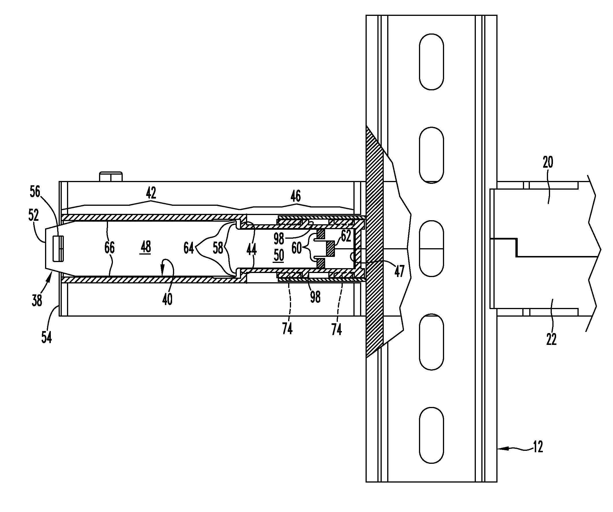
[0005]Manufacture of the base is facilitated by positively positioning part of the latch assembly in a fixed initial assembly position in the shells, completing mounting of the latch assembly and then shifting the assembly from the initial position to an operative position.
[0008]Positive location of the release member in the shells during assembly assures that the release member is in a known initial assembly position for receiving and forming a physical connection with the latch member. Shifting of the joined members toward the DIN rail frees the release member for operative movement of the assembly between latched and unlatched positions.

Problems solved by technology

Properly positioning the parts of the latch in the shells during assembly can be difficult.
Improper location of the parts during assembly of the shells increases the difficulty and cost of manufacturing bases.

Method used


Image

  • Latch assembly for mounting power supply base for a process fieldbus on a DIN rail and method
  • Latch assembly for mounting power supply base for a process fieldbus on a DIN rail and method
  • Latch assembly for mounting power supply base for a process fieldbus on a DIN rail and method

Examples


Embodiment Construction

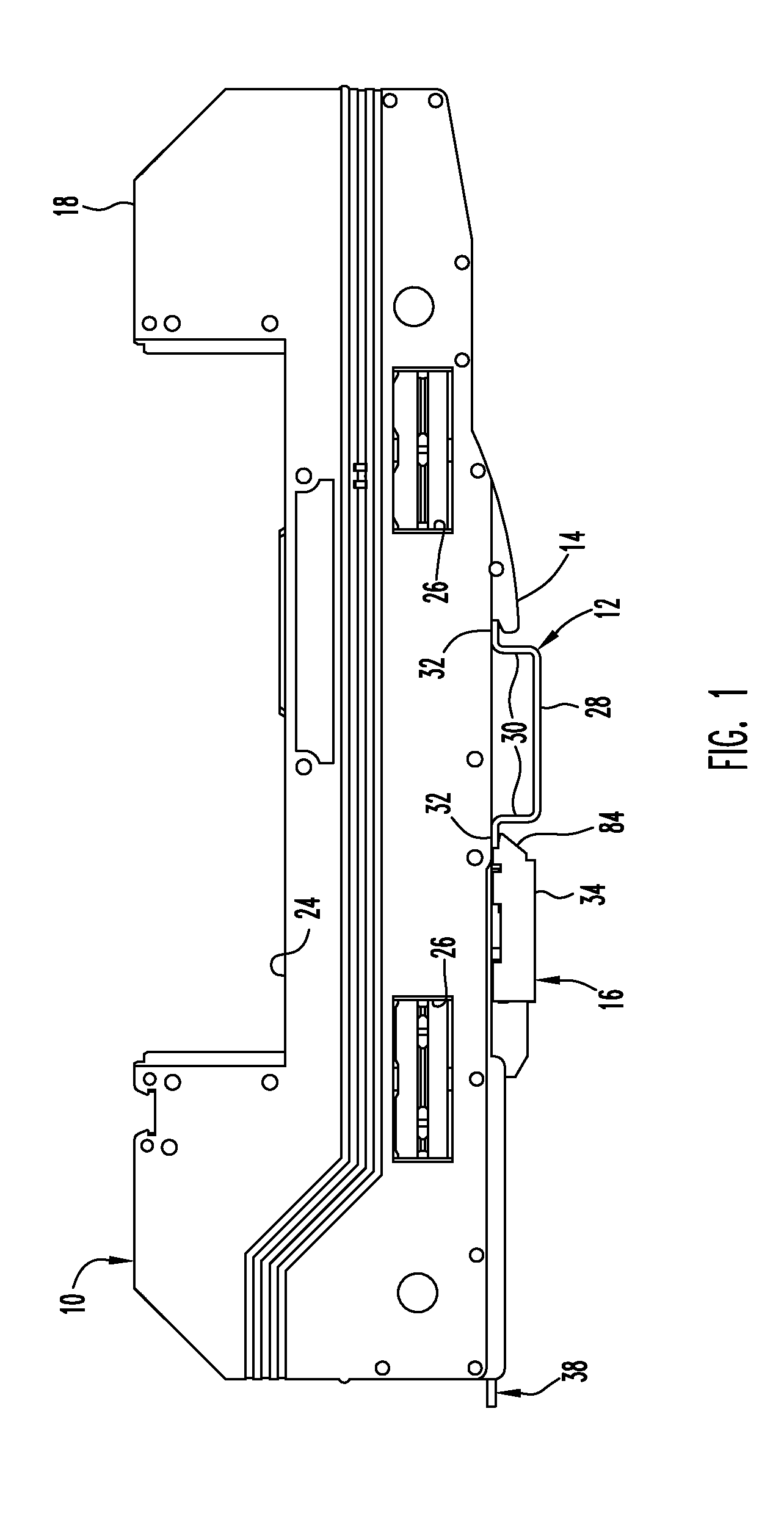
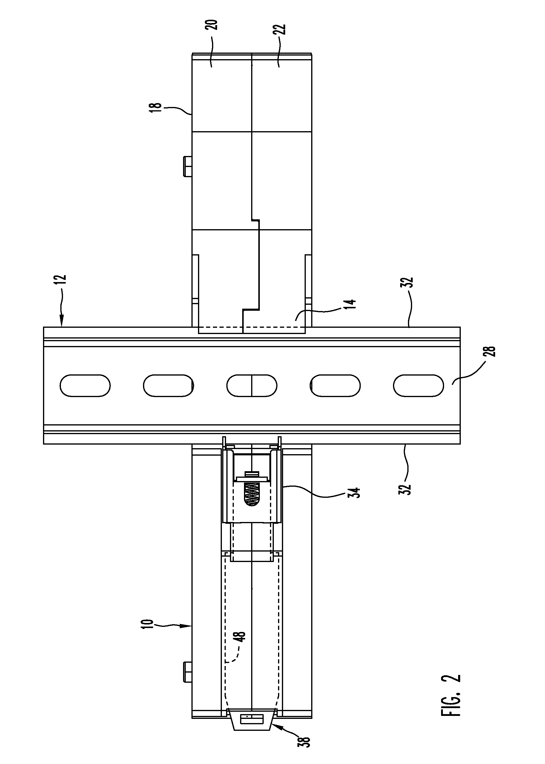
[0019]Power supply base 10 is removably mounted on elongate DIN rail or support 12 by DIN rail hook 14 on the bottom of the base and DIN rail latch assembly 16 on the bottom of the base on the opposite side of the rail from hook 14. The base 10 includes a hollow plastic body 18 formed from two hollow shells 20 and 22 joined together at an interface between the shells. The latch assembly extends between a DIN rail location at rail 12 and an actuation location at base end 54.

[0020]Module recess 24 is formed at the top of the base 10. A power conditioning module may be mounted in recess 24 for electrical connection with electronic components in the base, conductors in a process fieldbus connected to the base and a DC power source for the process fieldbus. The process fieldbus conductors and power supply conductors are connected to contact members on the base (not illustrated). Other types of electronic modules may be mounted in recess 24.

[0021]A power conditioning module mounted on bas...


PUM

PropertyMeasurementUnit
angleaaaaaaaaaa
angleaaaaaaaaaa
widthaaaaaaaaaa

Abstract

A base for mounting on a DIN rail includes a body and a latch assembly on the bottom of the body. The latch assembly has an elongate actuator extending to one side of the base and a latch member attached to the actuator for engaging the DIN rail. The release member is held on the base in an assembly position to facilitate mounting of the attachment member on the release member and the base, and is then shifted to an operative position.

Description

FIELD OF THE INVENTION[0001]The invention relates to latch assemblies for removably mounting a base, typically a power supply base, on a DIN rail, and to methods for forming a base with a DIN rail latch assembly.BACKGROUND OF THE INVENTION[0002]Electronic bases are conventionally removably latched on DIN rails or other mounting members. Each base typically includes a pair of hollow shells which house electronic components. The components have exposed contact members for forming electrical connections with the other electronic components outside the base. The base is assembled by placing the electronic components in the shells and then securing the shells together.[0003]A latch for securing the base on a DIN rail or other mounting element is typically mounted on the shells when the shells are joined together. Properly positioning the parts of the latch in the shells during assembly can be difficult. Improper location of the parts during assembly of the shells increases the difficulty...

Claims


Application Information

Patent Timeline
Patent Type & Authority Patents(United States)
IPC IPC(8): H01R13/60H01R13/66
CPCH01R9/2608Y10T29/49826
Inventor CORRELL, MICHAEL ANTHONYBARBER, TERRY LEE
Owner PHOENIX CONTACT DEVMENT & MFG
Learn More