Terminal connector for a regulator

a technology for connecting terminals and regulators, which is applied in the direction of vehicle connectors, line/current collector details, electrical apparatus, etc., can solve the problems of failing to secure a sufficient current capacity and establishing a connection, and achieve the effect of more secure connection of external terminals

Inactive Publication Date: 2012-07-24
HONDA MOTOR CO LTD
View PDF13 Cites 23 Cited by
  • Summary
  • Abstract
  • Description
  • Claims
  • Application Information

AI Technical Summary

Benefits of technology

[0011]Embodiments of the invention provide a terminal connector for a regulator, which, when a larger-capacity regulator is employed, makes a connection position of an external terminal more recognizable, makes it unlikely that the external terminal is connected to an incorrect position, and allows a more secure connection of the external terminal.
[0019]Embodiments of the invention provide non-obvious advantages over conventional terminal connectors for regulators. For example, according to an embodiment of the invention, the terminal connector includes multiple terminal units to which external terminals are individually connected. These terminal units are arranged in a width direction. The terminal units are each formed as a support base for screw-tightening, to which one of the external terminals is connected. An identification is marked on each of the terminal units. At least two of the terminal units are different from each other in width. Accordingly, by marking the identification on each of the terminal units, the connection positions of the external terminals are made easily recognizable.
[0021]Furthermore, in combination with the identification mark, an operation of incorrectly connecting the external terminal to the terminal unit can be avoided. For example, although the external terminal having a narrow width can be connected to the terminal unit having a wide groove width, this operation is made more easily avoidable. This leads to easier avoidance of incorrect assembling and reduction in the number of assembling steps.
[0023]In accordance with another embodiment of the invention, the terminal units are cathode-side connecting unit to which the external terminal at the cathode-terminal side of the battery is connected, a ground-side connecting unit which is connected to the ground, and to which the external terminal at the anode-terminal side of the battery is connected; and three generator-side connecting units to which the external terminals at the side of the generator are connected. This makes it possible to rectify, by the regulator, an alternating current generated by the generator and to supply the rectified current to the battery while adjusting the voltage.
[0025]In accordance with another embodiment of the invention, the identification mark includes a “+” symbol engraved in the cathode-side connecting unit, a “−” symbol engraved in the ground-side connecting unit, and a “˜” symbol engraved in each of the generator-side connecting units. Accordingly, the identification mark is less likely to disappear, and the identification of the terminal units is favorably made over an extended period of time.
[0026]In accordance with an embodiment of the invention, the width of the cathode-side connecting unit is formed wider than the widths of the ground-side connecting unit and the generator-side connecting units. The width of the ground-side connecting unit is formed identical to the widths of the generator-side connecting units. Accordingly, the width of the external terminal, which could be connected to the cathode-side connecting unit, can be made wider than the widths of the ground-side connecting unit and the generator-side connecting units. The external terminal, which could be connected to the cathode-side connecting unit, can be prevented from being connected to the ground-side connecting unit and the generator-side connecting units.

Problems solved by technology

Conventional connector units can only establish a connection, failing to secure a sufficient current capacity.

Method used


Image

  • Terminal connector for a regulator
  • Terminal connector for a regulator
  • Terminal connector for a regulator

Examples


Embodiment Construction

[0038]Embodiments of the invention will be described below in detail with reference to the accompanying drawings. Left, right, front, and rear in the description indicate directions based on the driver who rides on the vehicle. The accompanying drawings are intended to be seen in the direction of the reference numerals. The arrow with the word FRONT in the accompanying drawings represents the front of the vehicle.

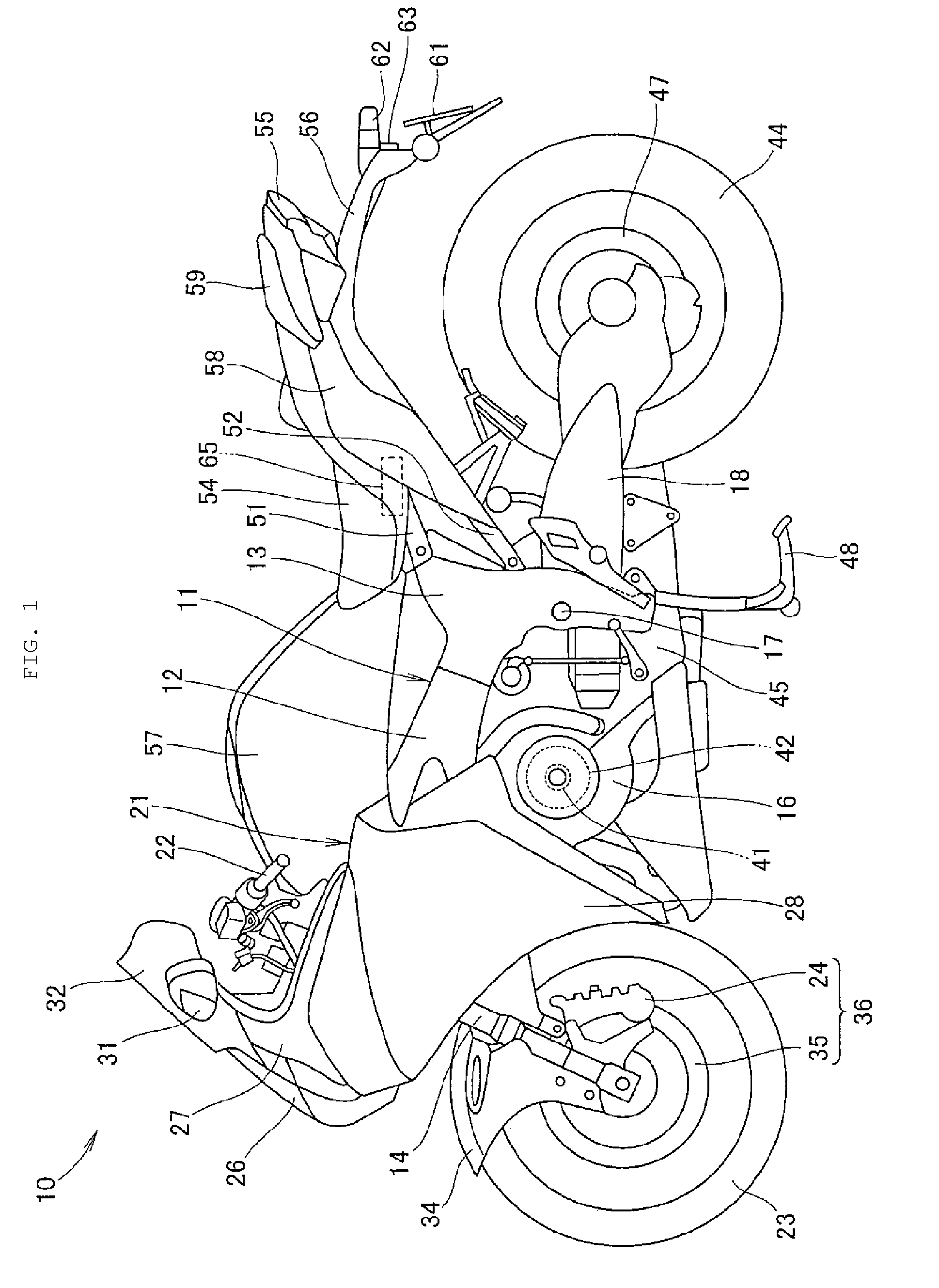
[0039]FIG. 1 is a side view of a vehicle, such as a motorcycle, including a terminal connector for a regulator, in accordance with an embodiment of the invention. A motorcycle 10 is shown in FIG. 1. The motorcycle 10 include a body frame 11 that serves as a framework of the motorcycle 10. The body frame 11 includes a pair of right and left main frames 12, 12 (only reference numeral 12 on the near side is illustrated), and a pair of right and left pivot plates 13, 13 (only reference numeral 13 on the near side is illustrated) connected to rear end portions of the main frames...


PUM

PropertyMeasurementUnit
widthaaaaaaaaaa
widthsaaaaaaaaaa
sizeaaaaaaaaaa

Abstract

A terminal connector for a regulator and a method for connecting an external terminal to the terminal connector are provided, whereby the regulator is configured to control an output of a generator provided to a motorcycle. The terminal connector is configured to connect the regulator and external terminals using bolts and nuts, and includes a plurality of terminal units. Each terminal unit is individually connected to an external terminal, and is configured in a width direction of the terminal connector. Each terminal unit is configured as a support base for screw-tightening, to which one of the external terminals is connected by screwing, and includes an identification mark. At least two of the terminal units have different widths.

Description

BACKGROUND[0001]1. Field[0002]Embodiments of the invention relate to a terminal connector for a regulator.[0003]2. Description of the Related Art[0004]Japanese Patent Application Publication No. 2008-245361 (“JP '361”) discloses a conventional terminal connector for a regulator provided in an AC generator.[0005]As illustrated in FIGS. 4(b) and 5(a) to 5(e) of JP '361, a regulator 14 includes a regulator board 14P and multiple lead wires extending from the regulator board 14P. The multiple lead wires are connected to an external connector terminal 200A1. A terminal A, a terminal RC, and a terminal L1, which are male connector terminals provided at an end portion of the external connector terminal 200A1, project to the inside of a connector unit 22, and are to be connected to an external connector unit.[0006]Currently, vehicles such as motorcycles require high-output AC generators and large-current regulators to handle increases electrical in loads. The increases in loads can come fro...

Claims


Application Information

Patent Timeline
Patent Type & Authority Patents(United States)
IPC IPC(8): H01R9/22
CPCH01R4/34H01R9/2441H01R9/2475H01R11/07Y10T29/49208H01R11/12H01R2201/26
Inventor KONDO, TETSUYAARAKAWA, KUNIAKISODA, HAJIME
Owner HONDA MOTOR CO LTD
Why Eureka
Try Eureka