Antenna with double groundings

a technology of double groundings and antennas, applied in the direction of antenna earthings, resonant antennas, radiating elements structural forms, etc., can solve the problems of reducing the reliability of wireless communication systems, reducing the reliability of conventional circularly polarized antennas, and losing the property of circular polarization. , to achieve the effect of flexible antenna arrangemen

Inactive Publication Date: 2012-07-24
HTC CORP
View PDF5 Cites 0 Cited by
  • Summary
  • Abstract
  • Description
  • Claims
  • Application Information

AI Technical Summary

Benefits of technology

[0009]The present invention provides an antenna with double groundings which is designed to include two ground parts for generating two orthogonal linearly polarized waves, and thereby forms a radiation wave approximating to circular polarization. Based on the technical means of the present invention, the gain of circular polarization radiation wave is achieved and the arrangement of the antenna becomes more flexible.

Problems solved by technology

In addition, the environment of mobile communication is full of interference and variables.
Among the above, the interference of multipath causes fading during the transmission of signal and greatly reduces the reliability of the wireless communication system.
However, in the current communication products, the design of the circularly polarized antenna, which has a structure of FIG. 2A, is usually limited to the shapes and systems of the products, and thus needs to be disposed on an unsymmetrical ground plane 130.
That is to say, the conventional circularly polarized antenna loses the property of circular polarization when applied to the current communication products, for the configuration and position thereof are limited.

Method used


Image

  • Antenna with double groundings
  • Antenna with double groundings
  • Antenna with double groundings

Examples


first embodiment

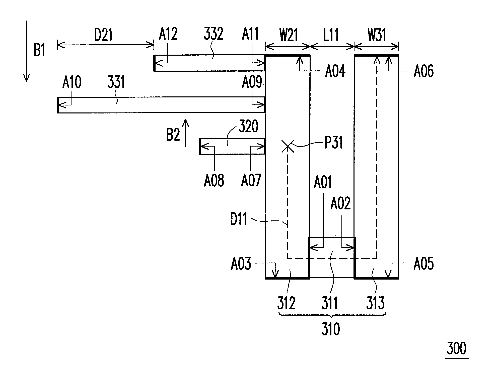
[0034]FIG. 3A illustrates a structural view of a planar inverted-F antenna according to one embodiment of the present invention. Referring to FIG. 3A, a planar inverted-F antenna 300 includes a body part 310, a feeding part 320, a first grounding part 331, and a second grounding part 332. Specifically, the body part 310 includes a first conductive element 311, a second conductive element 312, and a third conductive element 313.

[0035]To be more detailed, the first conductive element 311 has two ends, which are respectively marked as A01 and A02; the second conductive element 312 has two ends, respectively marked as A03 and A04; the third conductive element 313 has two ends, respectively marked as A05 and A06; the feeding part 320 has two ends, respectively marked as A07 and A08; the first grounding part 331 has two ends, respectively marked as A09 and A10; and the second grounding part 332 has two ends, respectively marked as A11 and A12.

[0036]As shown in FIG. 3A, the first end A01 o...

second embodiment

[0043]FIG. 3B illustrates a structural view of a planar inverted-F antenna according to another embodiment of the present invention. Referring to FIG. 3A and FIG. 3B, the main differences between the first and the second embodiments are the changes of the width of a body part 310′, the flowing direction and length of the current path D12, and the sequence and configuration of the feeding part 320, the first grounding part 331, and the second grounding part 332.

[0044]Specifically, in this embodiment, the body part 310′ includes a first conductive element 311′, a second conductive element 312′, and a third conductive element 313′. The current path D12 on the body part 310′ goes from a feeding point P32 through the ends A01 and A02 to the end A06. In view of the configuration of the elements in a planar inverted-F antenna 300′, the second end A07 of the feeding part 320 is electrically connected to the second conductive element 312′ via the feeding point P32. The first grounding part 3...

third embodiment

[0047]FIG. 3C illustrates a structural view of a planar inverted-F antenna according to yet another embodiment of the present invention. With reference to FIG. 3A and FIG. 3C, the main differences between the third and the above embodiments are the changes of the width of a body part 310″, the flowing direction and length of a current path D13, and the sequence and arrangement of the feeding part 320, the first grounding part 331, and the second grounding part 332.

[0048]Specifically, in this embodiment, the body part 310″ includes a first conductive element 311″, a second conductive element 312″, and a third conductive element 313″. The current path D13 on the body part 310″ goes from a feeding point P33 through the ends A01 and A02 to the end A06. In view of the configuration of the elements in a planar inverted-F antenna 300″, the second end A07 of the feeding part 320 is electrically connected to the second conductive element 312″ via the feeding point P33. The first grounding pa...


PUM


Abstract

An antenna with double groundings, including a body part, a feeding part, a first grounding part, and a second grounding part, is provided. The body part is electrically connected to the feeding part, the first grounding part, and the second grounding part respectively. The body part is corresponding to a resonance length to transmit and receive a radiation wave with a wavelength at an operating frequency. Wherein, a current path from the first grounding part to the feeding part along the body part is ½ times of the wavelength at the operating frequency, and a relative distance between the second grounding part and the first grounding part is ¼ times of the wavelength at the operating frequency.

Description

CROSS-REFERENCE TO RELATED APPLICATION[0001]This application claims the priority benefit of Taiwan application serial No. 98105651, filed on Feb. 23, 2009. The entirety of the above-mentioned patent application is hereby incorporated by reference herein and made a part of this specification.BACKGROUND OF THE INVENTION[0002]1. Field of the Invention[0003]The present invention is related to an antenna and particularly to an antenna with double groundings.[0004]2. Description of Related Art[0005]In view of the research of wireless communication, different systems have diversified frequencies and bandwidths, and require different designs of radiation patterns and polarizations of the wave radiated by the antenna from time to time. In addition, the environment of mobile communication is full of interference and variables. An antenna not only needs to coordinate the frequency, bandwidth, pattern of radiation wave, and polarization, but is required to overcome problems, such as interferenc...

Claims


Application Information

Patent Timeline
Patent Type & Authority Patents(United States)
IPC IPC(8): H01Q1/38
CPCH01Q1/48H01Q9/0421H01Q9/0428
Inventor TENG, PEI-LINGCHEN, YI-CHUN
Owner HTC CORP
Why Eureka
Try Eureka