Laser driving device and optical apparatus

a driving device and laser technology, applied in the field of laser driving devices, can solve the problems of increasing recording speed, reducing transmission band, and affecting the speed of recording, so as to reduce the number of signals transmitted, ease the length of routed wiring, and reduce the transmission bandwidth

Active Publication Date: 2012-07-24
SONY CORP
View PDF10 Cites 0 Cited by
  • Summary
  • Abstract
  • Description
  • Claims
  • Application Information

AI Technical Summary

Benefits of technology

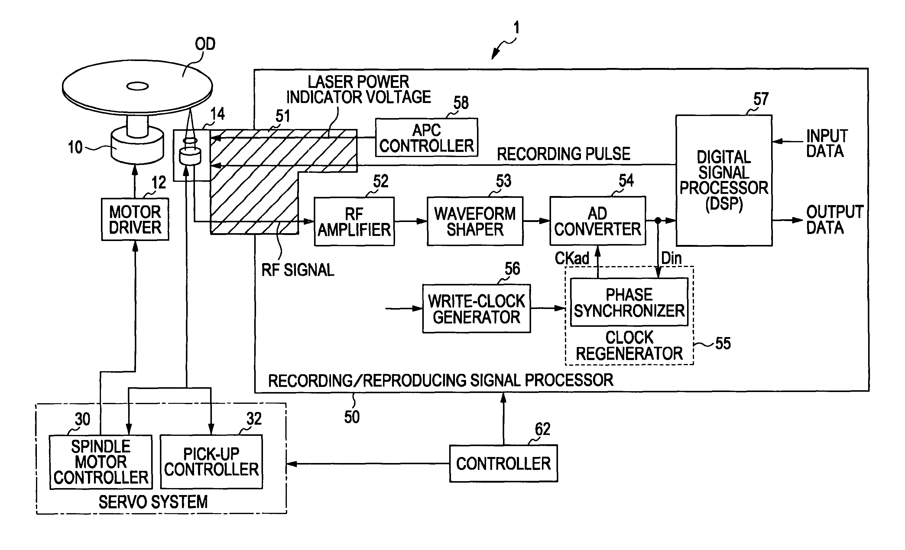
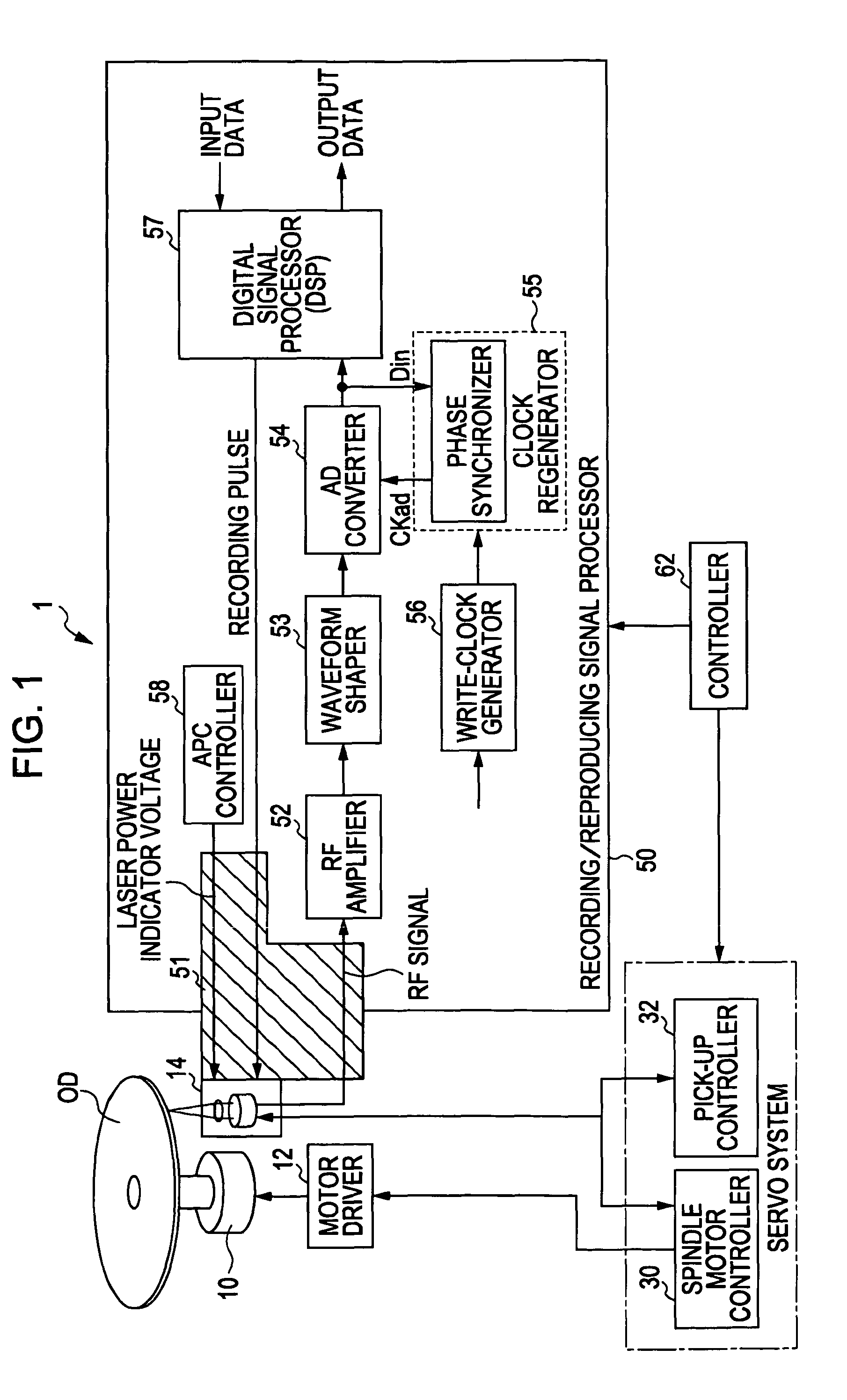
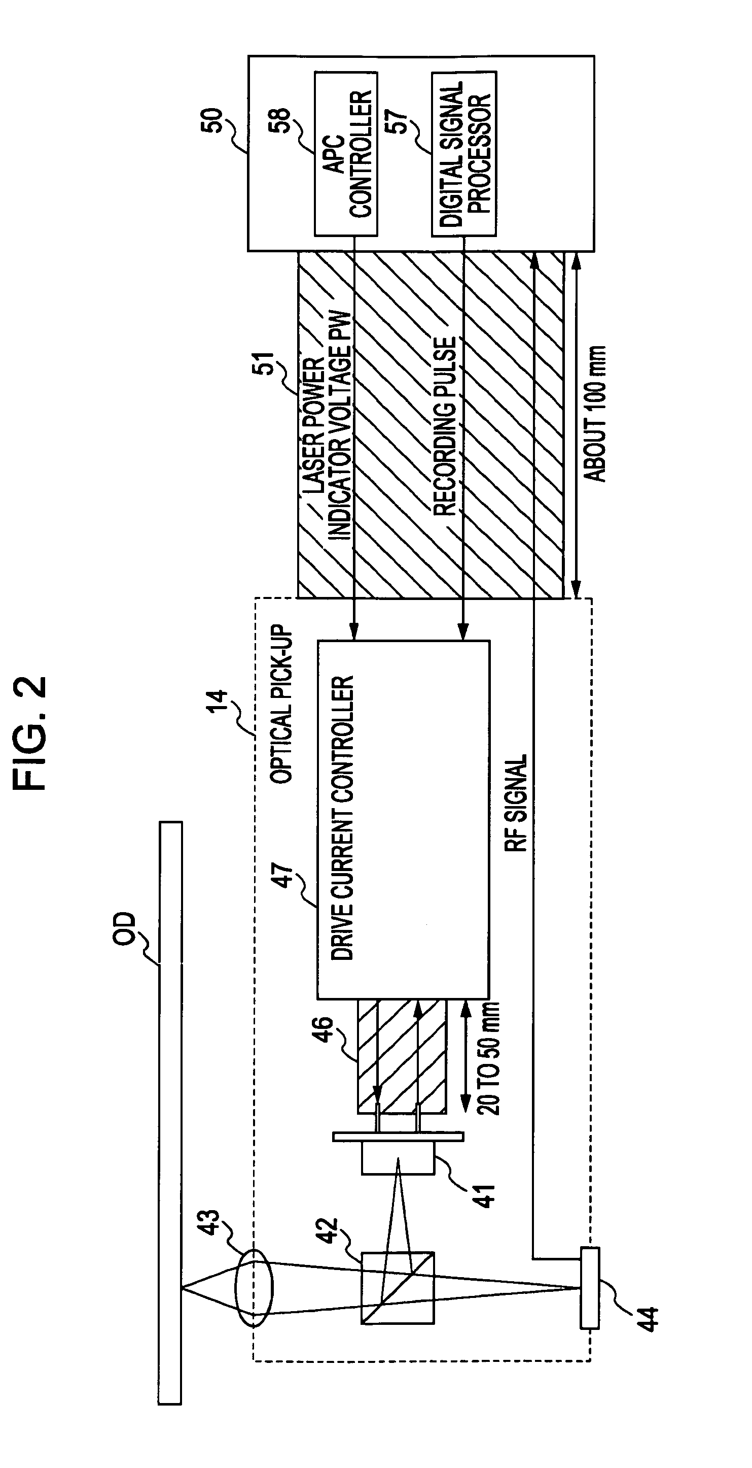
[0017]The laser driving device / optical apparatus may perform a process of storing signal patterns for recording-waveform control in a storage using the write strategy technology. Two different signals are used to generate a reference pulse and a switch pulse. Reference level information is read at the timing of a reference pulse. The remaining pieces of level information are read out one by one every switching pulse. Therefore, the process is provided as a simple process including power level information sequentially stored in signal patterns for recording-waveform control in a storage unit. Every time a reference material is acquired, reference level information is read out from the head of the reference pulse. Then, every time a switching pulse is acquired, each piece of other level information is read out every switching pulse. Since the number of types of transmitting signals is small, a problem of the decreased number of signals transmitted and the decreased transmission bandwidth are solved. In addition, this is because any trouble due to the space of signal wiring lines and the length of routed wiring is eased.

Problems solved by technology

At this time, the flexible substrate restricts a transmission band, so that the intervals of emission-timing signals will be hardly transmitted correctly, preventing an increase in recording speed.
Furthermore, the write strategy tends to be complicated to realize high density and high speed recording.
In other words, it may result in a decrease in transmission band due to an ensured arrangement space of the flexible substrate and the length of a routed wiring.

Method used


Image

  • Laser driving device and optical apparatus
  • Laser driving device and optical apparatus
  • Laser driving device and optical apparatus

Examples


first embodiment

Operation: First Embodiment

[0132]As shown in FIG. 10 and FIG. 11, data input is non-return zero data NRZIDATA. The length of a space is 2 T and the length of a mark is 2 T or more (in the figure, for example, 2 T, 3 T, 4 T, and 5 T). The maximum speed signal is 2 T repetition. When applying the write strategy technology, in this example, each space length 2 T corresponds a cool level (Cool) on the first half (1 T) and an erase level (Erase) on the second half (1 T). The mark length 2 T corresponds to an erase level on the first half (1 T) and the second half (1 T) corresponds to an overdrive level. The mark length 3 T corresponds to an erase level on the first 1 T, an overdrive level (O.D.) on the second 1 T, and a peak level (Peak) on the third 1 T.

[0133]The mark length 4 T corresponds to an erase level on the first 1 T, an overdrive level on the second 1 T, a peak level on the third 1 T, and an overdrive level on the fourth 1 T. The mark length 5 T corresponds to an erase level on...

second embodiment

Operation: Second Embodiment

[0149]As shown in FIG. 15 and FIG. 16, one reset signal RS and two edge signals ES_1 and ES_2 are used as input pulse signals, so that there are three input pulse signals in total.

[0150]For example, an edge pulse EP_1 is generated based on both the edges of the first edge signal ES_1. An edge pulse EP_2 is generated based on the both edges of the second edge signal ES_2. Then, the edge pulses EP_1 and EP_2 are ORed with each other to give one edge pulse EP. Subsequently, in a manner similar to the first embodiment, the edge pulse EP is supplied to readout switches 234_2 to 234_k of the emission level pattern storage 230. The subsequent steps are the same as those of the first embodiment. As is the case with the first embodiment, the use of two second transmission signals (an edge signal ES_1 and an edge signal ES_2) allows the edges of an edge signal ES that defines the timing of switching laser emission levels to be dispersed in two edge signals ES_1 and...

third embodiment

Operation: Third Embodiment

[0166]As shown in FIG. 20 and FIG. 21, two reset signals RS_1 and RS_2 and one edge signal ES are used as input pulse signals, so that there are three input pulse signals in total. A reset pulse RP_1 is generated on the basis of the rising edge or both the rising edge and the falling edge of the first reset signal RS_1. A reset pulse RP_2 is generated on the basis of the rising edge or both the rising edge and the falling edge of the second reset signal RS_2. A reset pulse RP_3 is then generated by logically multiplying the reset pulse RP_1 by the reset pulse RP_2 to give a reset pulse PR_3 and by logical addition thereof to give a reset pulse RP. When only the reset pulse RP_1 is an active high state, the storage information control unit 236 reads storage information from the register set 231_1, and sets the read information into the register set 231_0. When only the reset pulse RP_2 is an active high state, the storage information control unit 236 reads ...


PUM

PropertyMeasurementUnit
wavelength-aaaaaaaaaa
lengthaaaaaaaaaa
transmissionaaaaaaaaaa

Abstract

A laser driving device includes a storage unit that stores signal patterns for recording-waveform control representing level information of each divided driving signal to drive a laser device on a space and a mark based on the divided driving signals. Also, it includes a pulse generator that generates the reference pulse and the switching pulse based on a first transmission signal and a second transmission signal. The first transmission signal contains timing information for acquiring a reference pulse that represents a timing of repetitively switching between the space and the mark. The second transmission signal contains timing information for acquiring a switch pulse that represents a timing of switching the signals. Among level information for each of the signals in the storage, reference level information is read together with the reference pulse. Other level information after the reference level information is sequentially read for each switching pulse.

Description

BACKGROUND OF THE INVENTION[0001]1. Field of the Invention[0002]The present invention relates to a laser driving device (laser driving circuit) and an optical apparatus such as an optical disc apparatus using such a laser driving device (a recording apparatus using an optical disc).[0003]2. Description of the Related Art[0004]A recording / reproducing apparatus using a laser as an optical source has been used in various fields. For example, optical disc recording / reproducing apparatus (hereinafter, only referred to as an optical disc apparatus) has been attracting attention.[0005]As a laser used as a light source, a semiconductor laser using a semiconductor material has been widely used for various kinds of devices in recent years. This is because it is very small and responses to driving current at high speed.[0006]As a writable optical disc to be used as a medium for recording or reproducing data, a phase-change optical disc, a magnetic optical disc, and so on have been widely known...

Claims


Application Information

Patent Timeline
Patent Type & Authority Patents(United States)
IPC IPC(8): G11B7/00
CPCG11B7/0062
Inventor KURIHARA, TSUTOMUKIMURA, MOTOIYOKOYAMA, KOICHIYOSHIHARA, TOSHIAKI
Owner SONY CORP
Why Eureka
Try Eureka