
Vehicle drive power generation control apparatus

a technology of control apparatus and power generator, which is applied in the direction of engine-driven generator propulsion, process and machine control, electric devices, etc., can solve the problems of long time-consuming operation of hybrid vehicles, insufficient reduction of exhaust emission, and insufficient shortening of engine operation period, so as to reduce fuel consumption and exhaust emission.

Active Publication Date: 2012-07-24
DENSO CORP
View PDF42 Cites 21 Cited by
  • Summary
  • Abstract
  • Description
  • Claims
  • Application Information

AI Technical Summary

Benefits of technology

The present invention provides a control apparatus for drive power generators of a vehicle that reduces fuel consumption and exhaust emissions. The apparatus includes a remaining distance calculation section, an electric motor travelable distance estimation section, and a travel mode selection section. The remaining distance calculation section calculates the distance to the next external charge point where electric charging is possible. The electric motor travelable distance estimation section estimates the distance the vehicle can travel in an electric motor travel mode by stopping the internal combustion engine and supplying power from the charge storage device to the rotary electric machine used as the power generator. The travel mode selection section compares the remaining distance and the electric motor travelable distance and selects the travel mode based on the comparison result indicating whether the vehicle can or cannot travel to the next external charge point in the electric motor travel mode or the engine travel mode using the internal combustion engine as the power generator.

Problems solved by technology

Since the electric power cannot be charged from the external power source, the amount of exhaust emission cannot be reduced sufficiently.
In some cases, the hybrid vehicle has to stop for a long time in traveling toward the charge point or travel at low speeds by using the electric motor.
As a result, the period of operating the engine cannot be shortened sufficiently.
In addition, the engine must be operated at operation points, at which fuel consumption efficiency is low, during travel stop (idling), low speed travel and the like of the vehicle.
Thus, the fuel cost and exhaust emission cannot be reduced sufficiently.

Method used


Image

  • Vehicle drive power generation control apparatus
  • Vehicle drive power generation control apparatus
  • Vehicle drive power generation control apparatus

Examples


Embodiment Construction

[0026]An embodiment of the present invention will be described below with reference to the accompanying drawings.

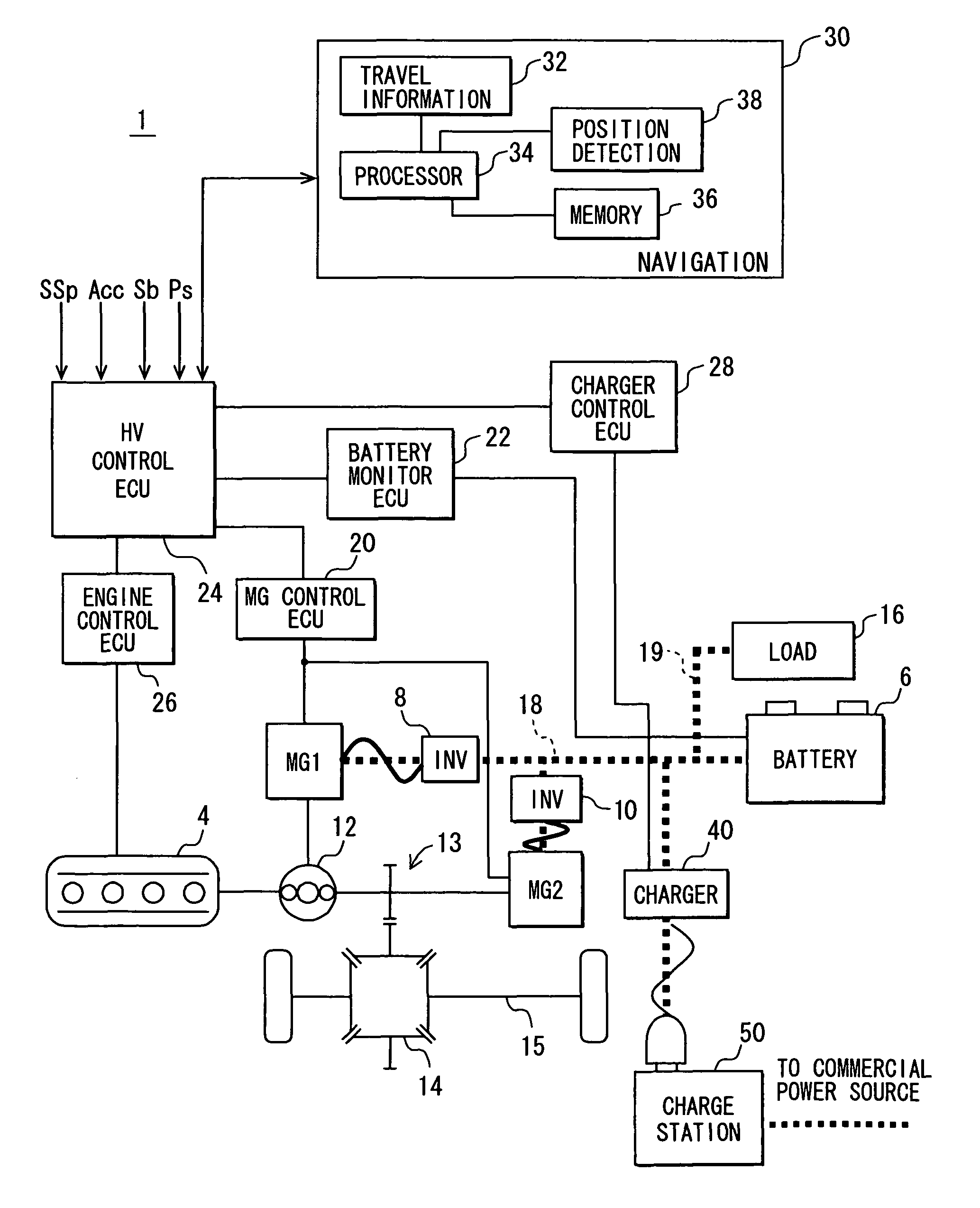
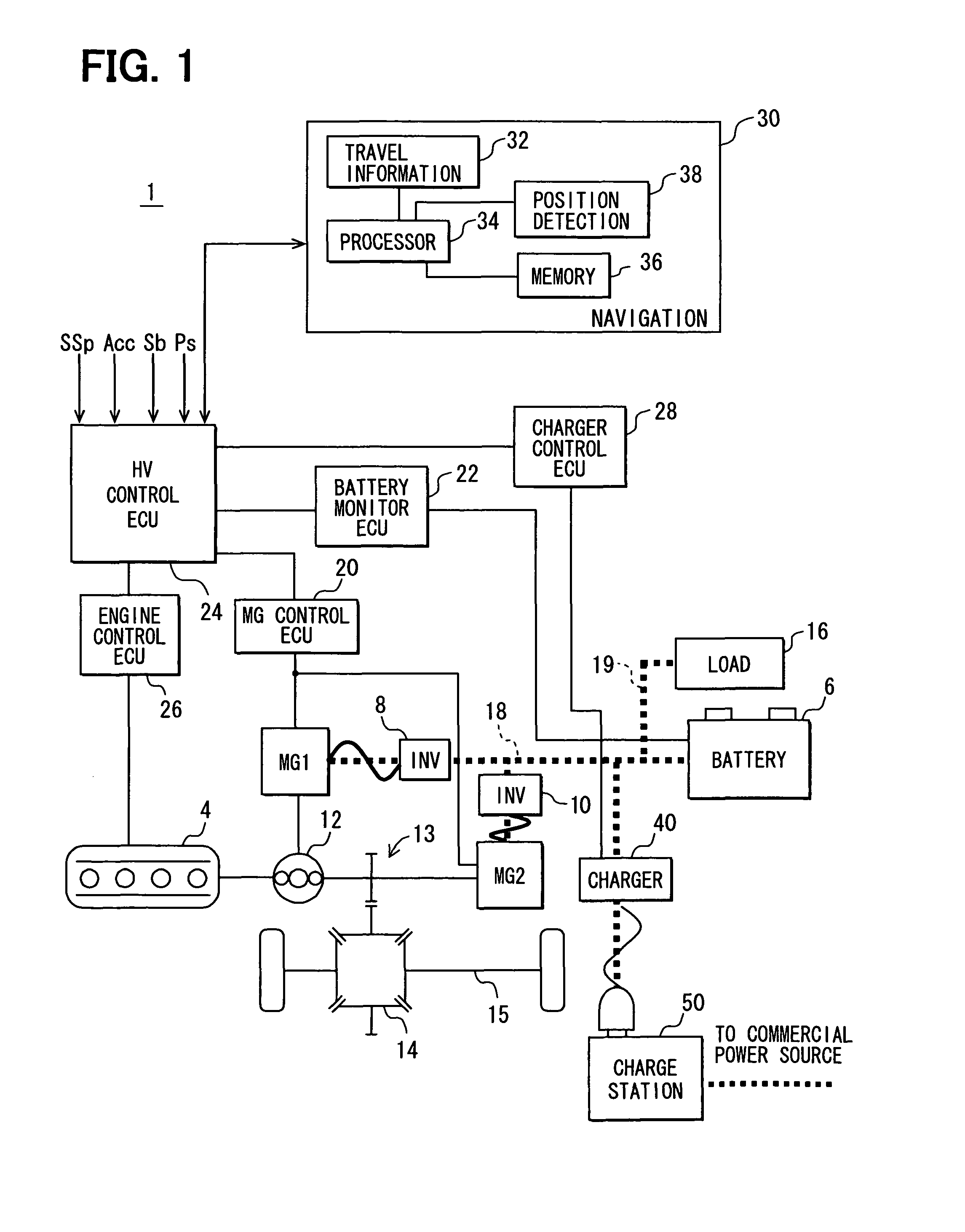
[0027]As shown in FIG. 1, a vehicle 1 is a series-parallel type hybrid vehicle, which has an engine 4 and two motor / generators MG1 and MG2 as drive power generators.

[0028]The engine 4 is an internal combustion engine that burns gasoline or diesel oil. The output shaft of the engine 4 is coupled to planetary gears of a planetary gear set 12. The output shaft of the first motor / generator MG1 is coupled to the sun gear of the planetary gear set 12. The input shaft of a speed reducer 13 is coupled to the ring gear of the planetary gear set 12. Thus, the planetary gear set 12 functions as a drive power divider. The planetary gear set 12 integrates the drive power from the engine 4 and the drive power from the first motor / generator MG1 and inputs the integrated drive power to the input shaft of the speed reducer 13. The planetary gear set 12 also divides the drive power from th...


PUM


Abstract

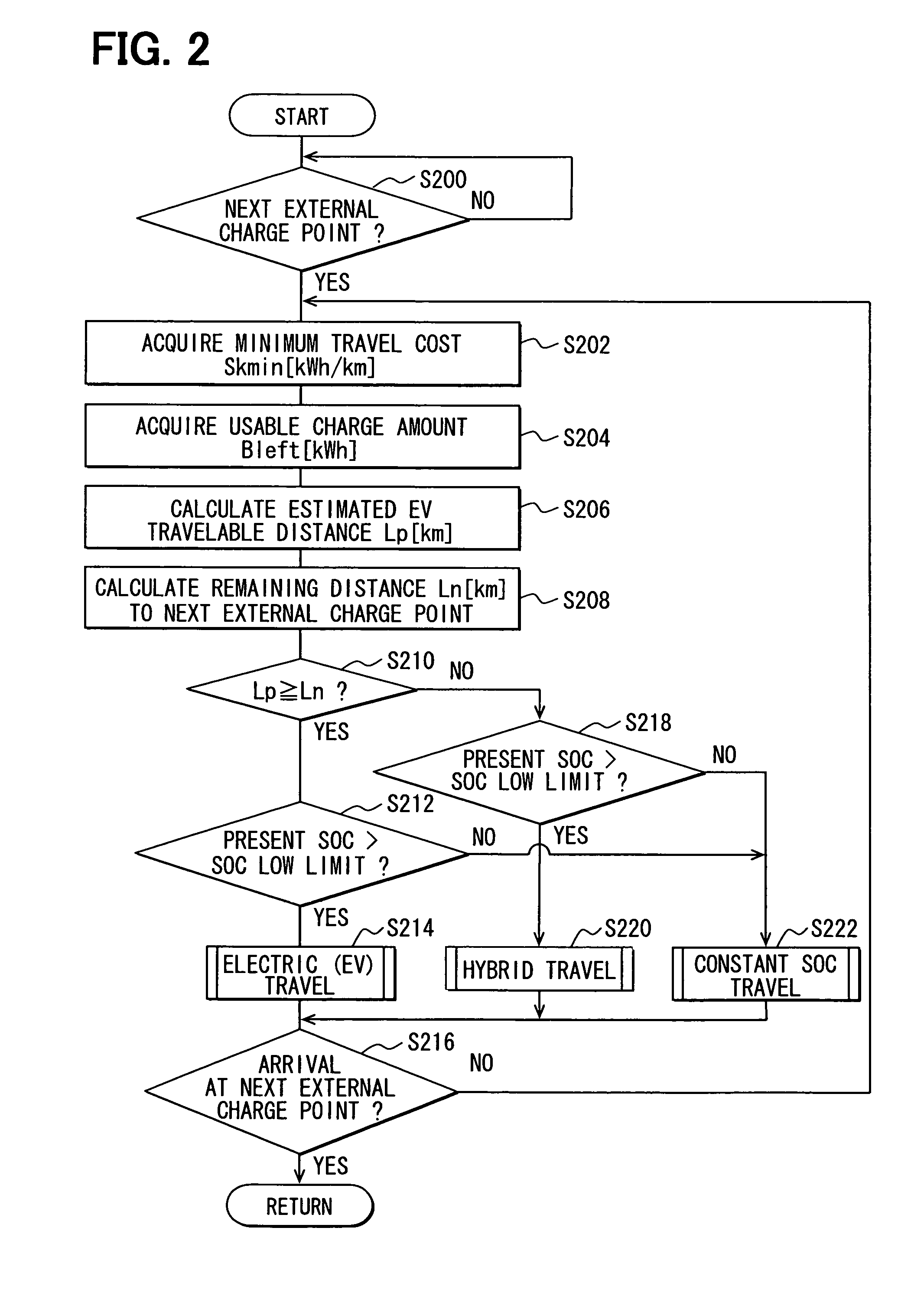
A hybrid vehicle control ECU calculates an estimated EV travelable distance based on a minimum travel cost and a usable charge amount of a battery, when a next external charge point, at which an external power source is available for charging, is set. The minimum travel cost indicates a minimum value of electric power amount consumed by a battery when a vehicle travels a unit distance. If the estimated EV travelable distance is longer, electric motor travel is selected estimating that it is possible to reach the next external charge point. If a remaining distance is longer and a present SOC is higher than a usable SOC lower limit, hybrid travel is selected. If the present SOC is lower than the usable SOC lower limit, a constant SOC travel is selected.

Description

CROSS REFERENCE TO RELATED APPLICATION[0001]This application is based on and incorporates herein by reference Japanese Patent Application No. 2009-24243 filed on Feb. 4, 2009.FIELD OF THE INVENTION[0002]The present invention relates to a control apparatus for drive power generators of a vehicle, which are used in a hybrid vehicle to control drive power generators.BACKGROUND OF THE INVENTION[0003]A conventional hybrid vehicle has, as a drive power generator for generating drive power to drive the drive shaft of the vehicle, an internal combustion engine, a rotary electric machine and an electric charge storage device, which transfers (supplies and receives) electric power to and from the rotary electric machine. In this hybrid vehicle, energy required for travel is charged to the charge storage device at charge stations, at which an electric power supply (commercial electric power source or the like) external to the vehicle is available (for example, patent documents 1 and 2). By usi...

Claims


Application Information

Patent Timeline
Patent Type & Authority Patents(United States)
IPC IPC(8): B60L9/00B60L11/00B60K6/445B60L50/16B60W10/06B60W10/08B60W10/26B60W20/00
CPCB60K6/365B60K6/445B60W10/06B60W10/08B60W10/26B60W20/00G06Q50/06B60K1/02B60L2240/423B60L2240/486B60W2510/244B60W2520/10B60W2540/10B60W2540/12B60W2540/16B60W2550/402B60W2710/0666B60W2710/083Y02T10/56Y02T10/6239Y02T10/6269Y02T10/6286Y02T10/642Y02T10/84B60W2556/50Y02T10/40Y02T10/62Y02T10/64B60W20/12
Inventor SAKAMOTO, AKIRATANI, KEISUKEYAMADA, KAZUNAO
Owner DENSO CORP
Learn More