
Vehicle recovery and traction ladder

a technology of traction ladders and sand ladders, which is applied in the direction of rolling resistance optimization, railway tracks, constructions, etc., can solve the problems of low traction of ladders, difficulty in placing ladders in front of tyres, and heavy sand ladders, so as to increase the resistance of strengthening ribs to deformation, increase the traction of ground, and reduce the effect of slipping

Inactive Publication Date: 2012-07-31
MAXTRAX AUSTRALIA PTY LTD
View PDF10 Cites 22 Cited by
  • Summary
  • Abstract
  • Description
  • Claims
  • Application Information

AI Technical Summary

Benefits of technology

[0007]Embodiments of the present invention provide a ladder for supporting a vehicle and providing traction that is light weight and cost effective or at least provides the user with a useful or commercial choice.SUMMARY OF THE INVENTION
[0020]Preferably the vehicle ladder is formed with an underside of a shape complementary to the topside in order that two or more of the vehicle ladders can be stacked one on top of the other. Stacking the ladders to form a lamination of them results in a composite ladder of increased strength which may be advantageous for use with particularly heavy vehicles.

Problems solved by technology

In addition corduroy tracks require a relatively large quantity of timber, only a relatively small quantity of which is actually used to support vehicles.
This type of sand ladder is generally heavy and difficult to place in front of a tyre.
In addition, in wet or muddy terrain these ladders provide little or no traction.
However, such expanded mesh is generally deformed when used for the recovery of a 4WD, i.e. four-wheel-drive, vehicle.
This is generally because in order for such a ladder to have sufficient strength to support a 4WD repeatedly it needs to be of a gauge that would render it too heavy for ready positioning in front of the wheels of a vehicle.
However, wheel spin on this type of plastic grating generally results in the grating being heat effected, either in melting by friction the top surface of the grating or causing the grating to plastically deform.
An articulated series of plastic ribbed members that is light weight has been tried but provides little support for a vehicle.

Method used


Image

  • Vehicle recovery and traction ladder
  • Vehicle recovery and traction ladder
  • Vehicle recovery and traction ladder

Examples


Embodiment Construction

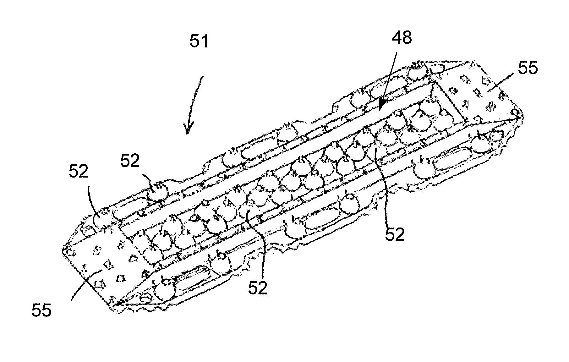
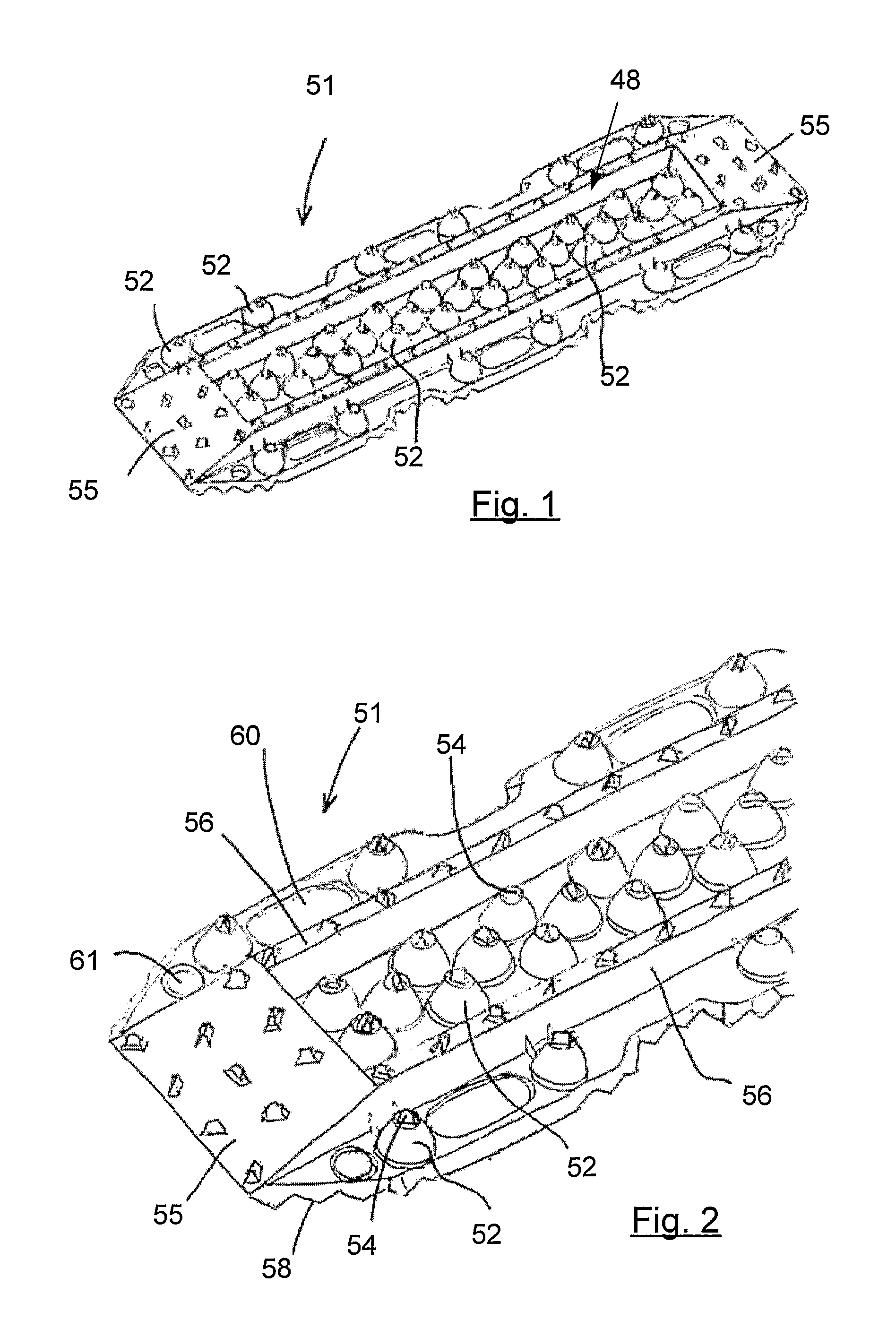
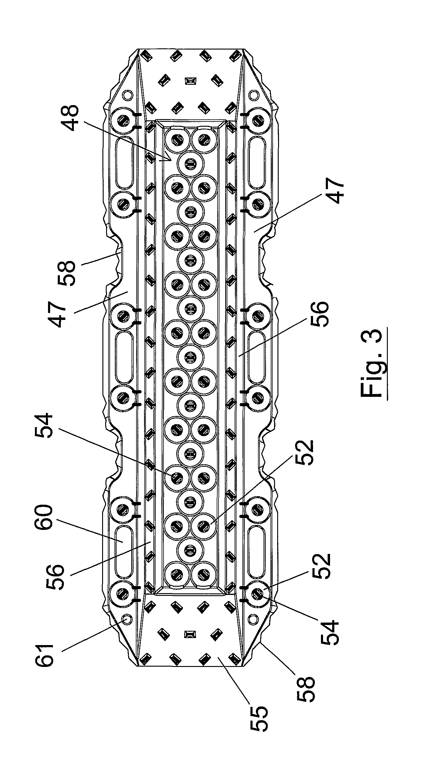
[0030]FIGS. 1 to 4 show an elongate vehicle ladder 51 in accordance with a preferred embodiment of the present invention. The vehicle ladder 51 has a long axis in which direction a vehicle's wheels are intended to roll in use. Ladder 51 has a topside into which a recessed portion 48 is formed. A plurality of traction members 52 extend from the floor of the recessed portion to support a vehicle tire in use. Other traction members are disposed along the outside edges of the vehicle ladder. The traction members 52 are frustoconical in shape with the traction members in the recessed portion of the vehicle ladder 51 being arranged in an array of rows and ranks. In the present embodiment, each row and each rank includes a triplet of traction members 52. There is further provided a pair of parallel rows of traction members 52 which are each located along either side of the vehicle ladder 51.

[0031]At the tip of the traction members 52 extend respective projections 54 that comprise tread eng...


PUM


Abstract

A lightweight vehicle ladder for the recovery and traction of vehicles includes a central recessed portion (48) bordered by longitudinal strengthening ribs (56) and ramps (55) at either end. A plurality of traction members (52), each of which terminates in an upper tire engagement member (54) are disposed within the recessed portion and thereby somewhat protected from the ingress of mud during use in order that traction may be maintained. The underside and topside of the vehicle are formed with complementary shapes in order that a number of the ladders may be stacked one on top of the other to form a laminate of increased strength for application with particularly heavy vehicles.

Description

[0001]The present invention relates to a vehicle support or “ladder” for a vehicle.[0002]Vehicle ladders find a variety of applications. Permanently or temporarily fixed ladders have been used to form vehicle tracks on soft or unprepared road bases. For example, over soft sand or other soft terrain, the National Park authority forms tracks using laterally fixed timber lengths, so called “timber corduroy tracks”. Similar constructions are often used for boat ramps and other soft or slippery vehicle paths where traction is an issue. Corduroy tracks are relatively high maintenance requiring the timber lengths to be regularly replaced. In addition corduroy tracks require a relatively large quantity of timber, only a relatively small quantity of which is actually used to support vehicles.[0003]Vehicle ladders also find use as recovery equipment for providing improved traction in a form that can be placed in front of a vehicle's tyre to enable the vehicle to extricate itself from mud or s...

Claims


Application Information

Patent Timeline
Patent Type & Authority Patents(United States)
IPC IPC(8): E01B23/00
CPCB60B39/12Y02T10/86
Inventor MCCARTHY, BRADLEY JOHN
Owner MAXTRAX AUSTRALIA PTY LTD
Learn More