Deposited microarchitectured battery and manufacturing method

a microarchitectured battery and manufacturing method technology, applied in the field of energy storage systems, can solve the problems of loss of the size advantage of the mems device, and achieve the effects of reducing energy losses, wide-spread utilization of the mems device, and increasing storage capacity

Active Publication Date: 2012-07-31
RGT UNIV OF MICHIGAN
View PDF11 Cites 74 Cited by
  • Summary
  • Abstract
  • Description
  • Claims
  • Application Information

AI Technical Summary

Benefits of technology

[0007]Embodiments of the present invention relate to microarchitectured batteries. These batteries can be used to create microscopic footprints, typically on the order of 1 mm2, and can be integrated directly into MEMS devices at the time of manufacture. Microarchitectured batteries have the potential to overcome the energy and power limitations of the past for MEMS, and will enable the widespread utilization of MEMS devices for creating wireless sensor networks for environmental or bio-medical applications; this is because power sources can be created which are of the same scale as other components of the system. By using improved fabrication processes to deposit battery materials, energy losses can be reduced and storage capability increased, enabling microbatteries with sizes that can be integrated with MEMS and meet their lifetime requirements.

Problems solved by technology

The size advantage of the MEMS device is lost if the battery is large.
Physical limitations of the electrode materials, separators, and electrolyte dictate their separate manufacture, and subsequent coupling of the battery to the MEMS device.

Method used


Image

  • Deposited microarchitectured battery and manufacturing method
  • Deposited microarchitectured battery and manufacturing method
  • Deposited microarchitectured battery and manufacturing method

Examples


Embodiment Construction

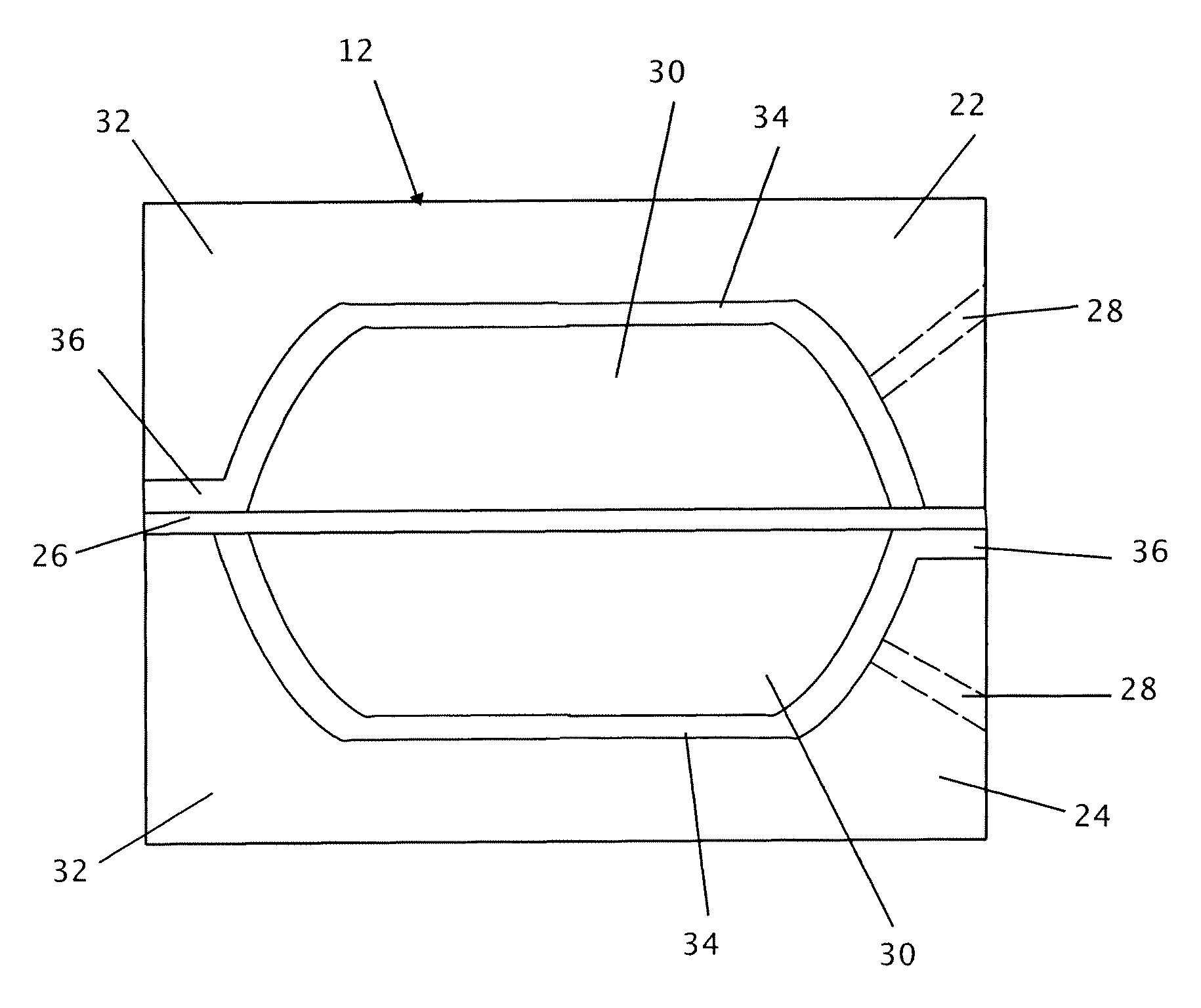
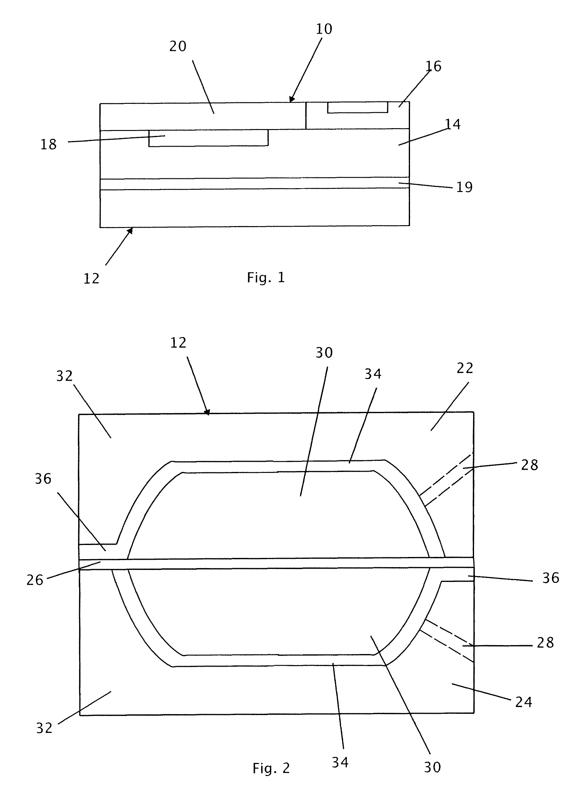
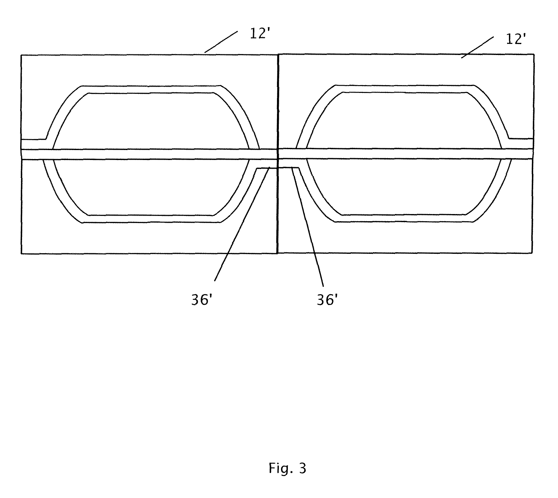
[0011]MEMS devices may benefit from a thin-film, microarchitectured, deposited battery that can be manufactured with or in a manner compatible with the manufacture of the MEMS device. A microbattery may be manufactured using processing techniques used for MEMS devices themselves. In this manner, the microbattery may be manufactured to have a footprint no larger than the device itself, may be manufactured during the processing or using the same processing techniques as the MEMS device. The microbattery may be directly coupled to the MEMS device, eliminating additional process steps. Other microarchitecturing processes can be applied to the substrates to create spacing, connections or microchannels for electrolyte, e.g. laser machining, micro-drilling, micro-cutting or similar processes. While several embodiments of the invention are described in connection with battery structures suitable for combination with MEMS devices, the techniques are scalable to larger dimensions. Therefore, ...


PUM

PropertyMeasurementUnit
thickaaaaaaaaaa
thickaaaaaaaaaa
diameteraaaaaaaaaa

Abstract

A battery includes a first portion including a substrate having formed thereon a current collector and an anode electrode material. A second portion is formed on a substrate and includes a current collector and a cathode electrode material. The first portion is joined to the second portion and a separator is disposed between the first portion and the second portion as joined to separate the anode electrode material from the cathode electrode material. An electrolyte is placed in contact with the anode electrode material, the cathode electrode material and the separator.

Description

CROSS-REFERENCE TO RELATED APPLICATIONS[0001]This application claims priority to and benefit from U.S. Provisional Patent Application Ser. Nos. 60 / 909,183, filed Mar. 30, 2007 entitled Micromachined Battery and 60 / 938,232, filed May 16, 2007 entitled Micromachined Battery, the disclosures of which are hereby incorporated herein by reference for all purposes.GOVERNMENT FUNDING[0002]The U.S. Government may have certain rights in this invention as provided for by the terms of Contract No. EEC 9986686 awarded by The National Science Foundation—Wireless Integrated Microsystems Engineering Research Center (NFS-WIMS ERC).TECHNICAL FIELD[0003]This patent relates to energy storage systems. More particularly, this patent relates to a deposited microarchitectured battery system and a design and manufacturing method for the same.BACKGROUND[0004]Many micro-electromechanical systems (MEMS) require a power source of electrical energy. In some instances electrical power is provided by a coupled bat...

Claims


Application Information

Patent Timeline
Patent Type & Authority Patents(United States)
IPC IPC(8): H01M2/14H01B13/00H01M6/42H01M4/13H01M10/052H01M10/0525H01M10/36H01M50/209
CPCH01M2/1061H01M4/13H01M6/40H01M10/0436H01M10/052H01M10/0525Y02E60/122Y02E60/10H01M50/209Y02P70/50
Inventor SASTRY, ANN M.ALBANO, FABIO
Owner RGT UNIV OF MICHIGAN
Why Eureka
Try Eureka