
Switched impedance synthesis transmit antenna matching system for electrically small antenna radiators

a technology of impedance synthesis and transmit antenna, which is applied in the direction of antennas, substation equipment, and electricly long antennas, etc., can solve the problems of system bound by the limit of bode-fano, limit the possible modulation bandwidth, and electrical stress on the power amplifier in these mismatch conditions, so as to achieve efficient transmission of broadband signals

Active Publication Date: 2012-07-31
ROCKWELL COLLINS INC
View PDF5 Cites 5 Cited by
  • Summary
  • Abstract
  • Description
  • Claims
  • Application Information

AI Technical Summary

Benefits of technology

[0011]It is an advantage of the present invention to efficiently transmit broadband signals from an electrically short antenna.
[0012]The present invention is a system and method for matching an electrically short antenna to a power amplifier, which invention is designed to satisfy the aforementioned needs, provide the previously stated objects, include the above-listed features, and achieve the already articulated advantages.
[0013]Accordingly, the present invention is a system and method including a plurality of circuits each configured for synthesizing an arbitrary impedance, arranged in a configuration so as to permit efficient transmission of a broadband signal over an electrical short antenna.

Problems solved by technology

For electrically short antennas particularly, this high ‘Q’ limits the possible modulation bandwidth.
While it is possible, with passive components, to match a narrow-band antenna to a single (carrier) frequency, the impedance mismatch presented to the modulation sideband frequencies has the effect of attenuating them, while causing electrical stress to the power amplifier in these mis-match conditions.
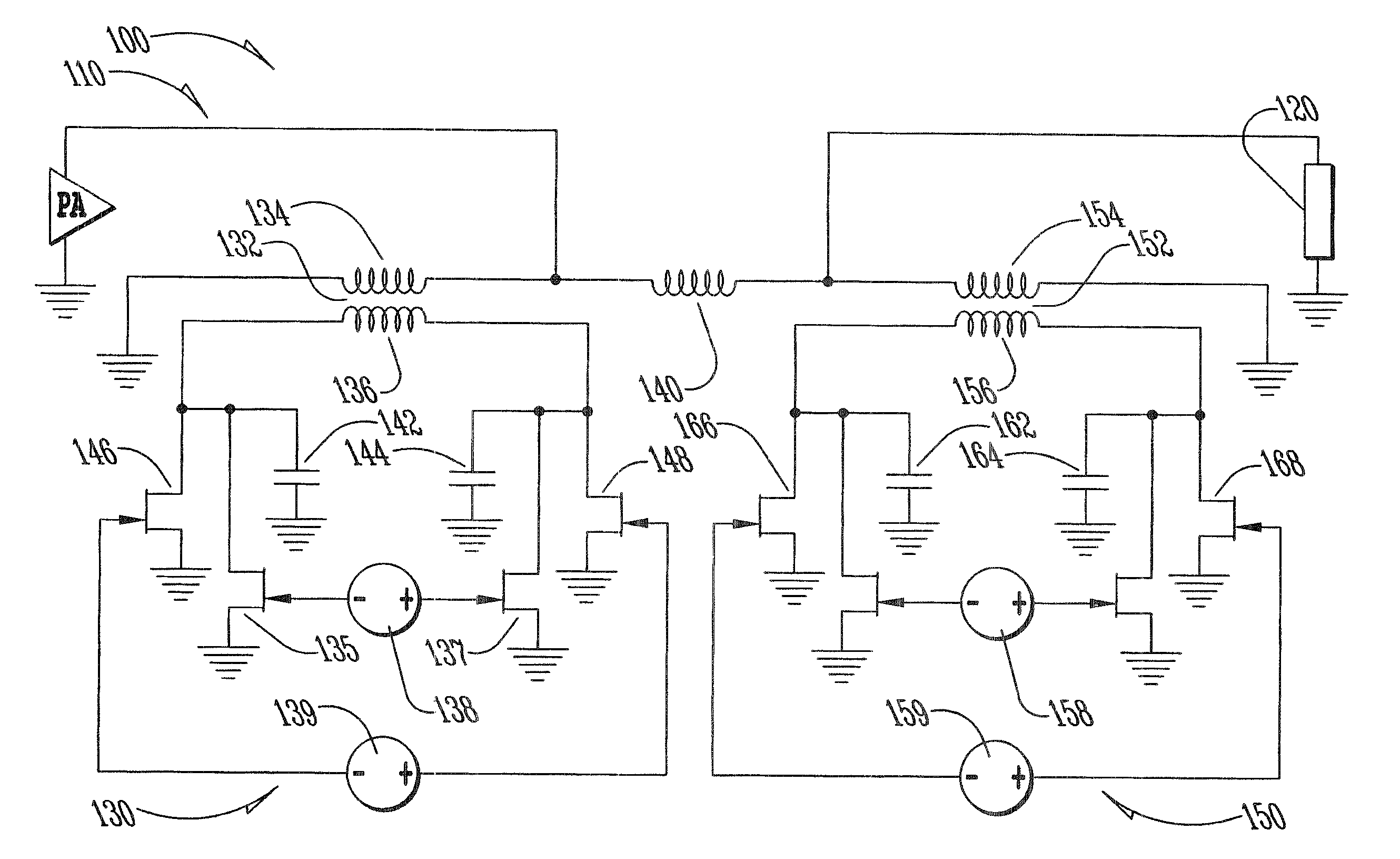
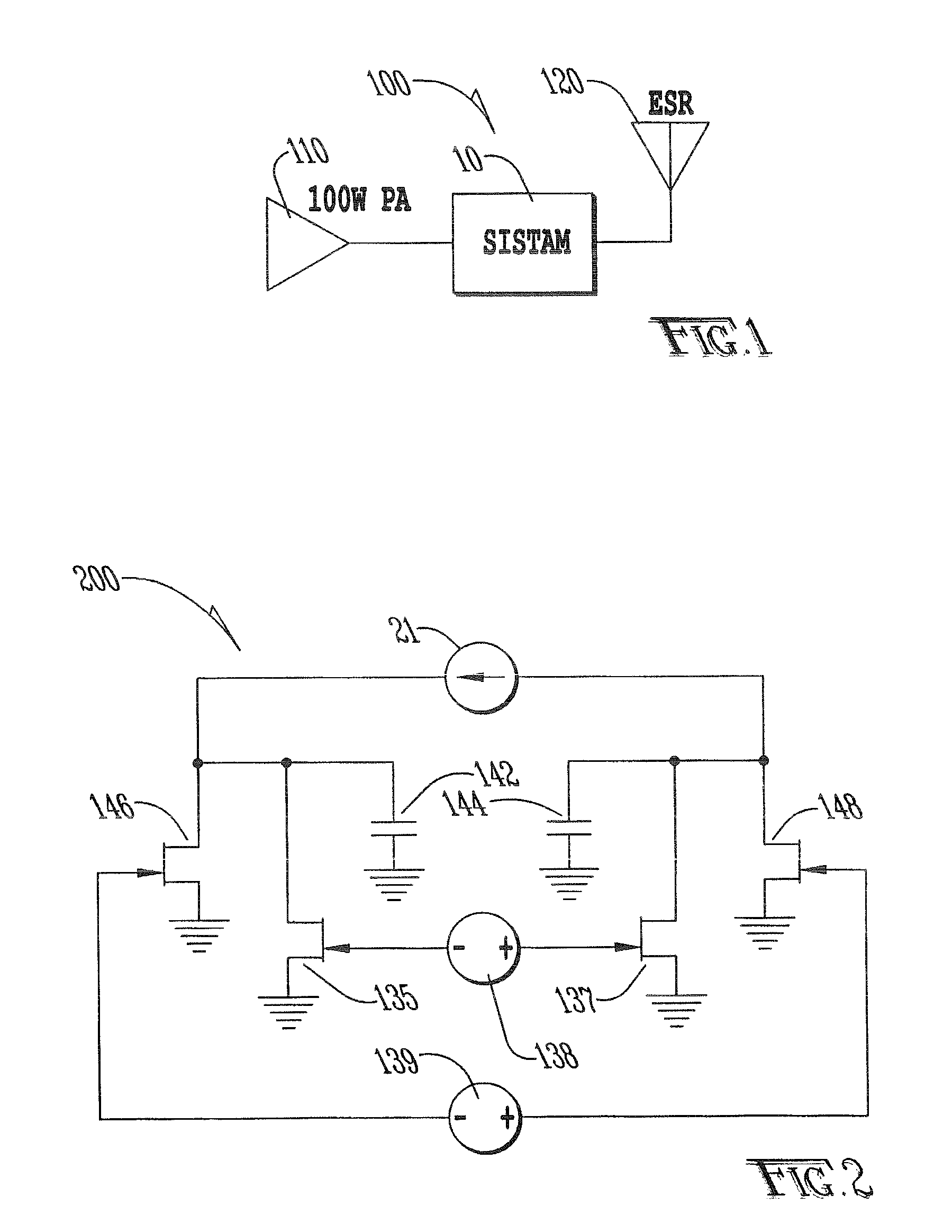
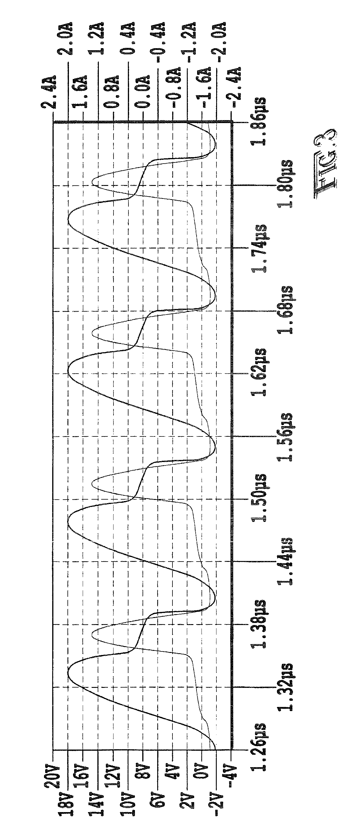
While effective in extending usable bandwidth, that system is still ultimately bound by the Bode-Fano limit.
However, because of the limited dynamic range and electrical inefficiency of the Non-Foster circuit elements, these approaches are often impractical in transmit applications.

Method used


Image

  • Switched impedance synthesis transmit antenna matching system for electrically small antenna radiators
  • Switched impedance synthesis transmit antenna matching system for electrically small antenna radiators
  • Switched impedance synthesis transmit antenna matching system for electrically small antenna radiators

Examples


Embodiment Construction

[0018]The following description is focused upon the system and method of the present invention in association with transmit antennas. It should be understood that this use of transmit antennas is merely an example, and receive antennas could be utilized as well.

[0019]Now referring to FIGS. 1-4, there are shown systems of the present invention which utilize techniques of load modulation to dynamically vary impedance matching and transformation of a narrow-bandwidth antenna to a power amplifier generating a complex modulation waveform, and to synthesize a network bearing a flat amplitude response and a group delay over the modulation bandwidth.

[0020]In the simplest case, a narrow bandwidth antenna is modeled as a series resonant L-R-C circuit. Placing a dynamically-controlled, variable reactive element in series with the antenna allows the reactive component of the antenna impedance to be subtracted at any given frequency. For a constant envelope, frequency-or-phase modulated signal, ...


PUM


Abstract

A system for transmitting a broadband signal over an electrically short antenna which includes a plurality of switched impedance synthesis transmit antenna matching circuits which are dynamically controlled with knowledge of the transmitting broadband signal to match the dynamic impedance of the electrically short antenna during transmission.

Description

FIELD OF THE INVENTION[0001]The present invention generally relates to an impedance matching system for electrically small antennas which comprises a plurality of customizable building block circuits each configured for synthesizing an arbitrary impedance.BACKGROUND OF THE INVENTION[0002]For many years, It has been well understood that the performance of an antenna diminishes as its dimension, as a fraction of the electrical wavelength, falls significantly below λ / 2. The ‘Q’ of an electrically short antenna is inversely proportional to the cube of its electrical length. For electrically short antennas particularly, this high ‘Q’ limits the possible modulation bandwidth.[0003]While it is possible, with passive components, to match a narrow-band antenna to a single (carrier) frequency, the impedance mismatch presented to the modulation sideband frequencies has the effect of attenuating them, while causing electrical stress to the power amplifier in these mis-match conditions.[0004]Ano...

Claims


Application Information

Patent Timeline
IPC IPC(8): H04B1/04
CPCH04B1/0458
Inventor CRIPE, DAVID W.PATTEN, SCOTT L.WOLF, JEREMIAH D.WEST, JAMES B.
Owner ROCKWELL COLLINS INC
Learn More