Trolley braking system

a technology of braking system and roller, which is applied in the direction of rope railway, building scaffold, roads, etc., can solve the problems of wet conditions and hazards, and achieve the effects of increasing the braking force generated against the cable, increasing the displacement of the rider's weight, and increasing the speed

Active Publication Date: 2012-08-07
ADVENTURE HLDG
View PDF34 Cites 18 Cited by
  • Summary
  • Abstract
  • Description
  • Claims
  • Application Information

AI Technical Summary

Benefits of technology

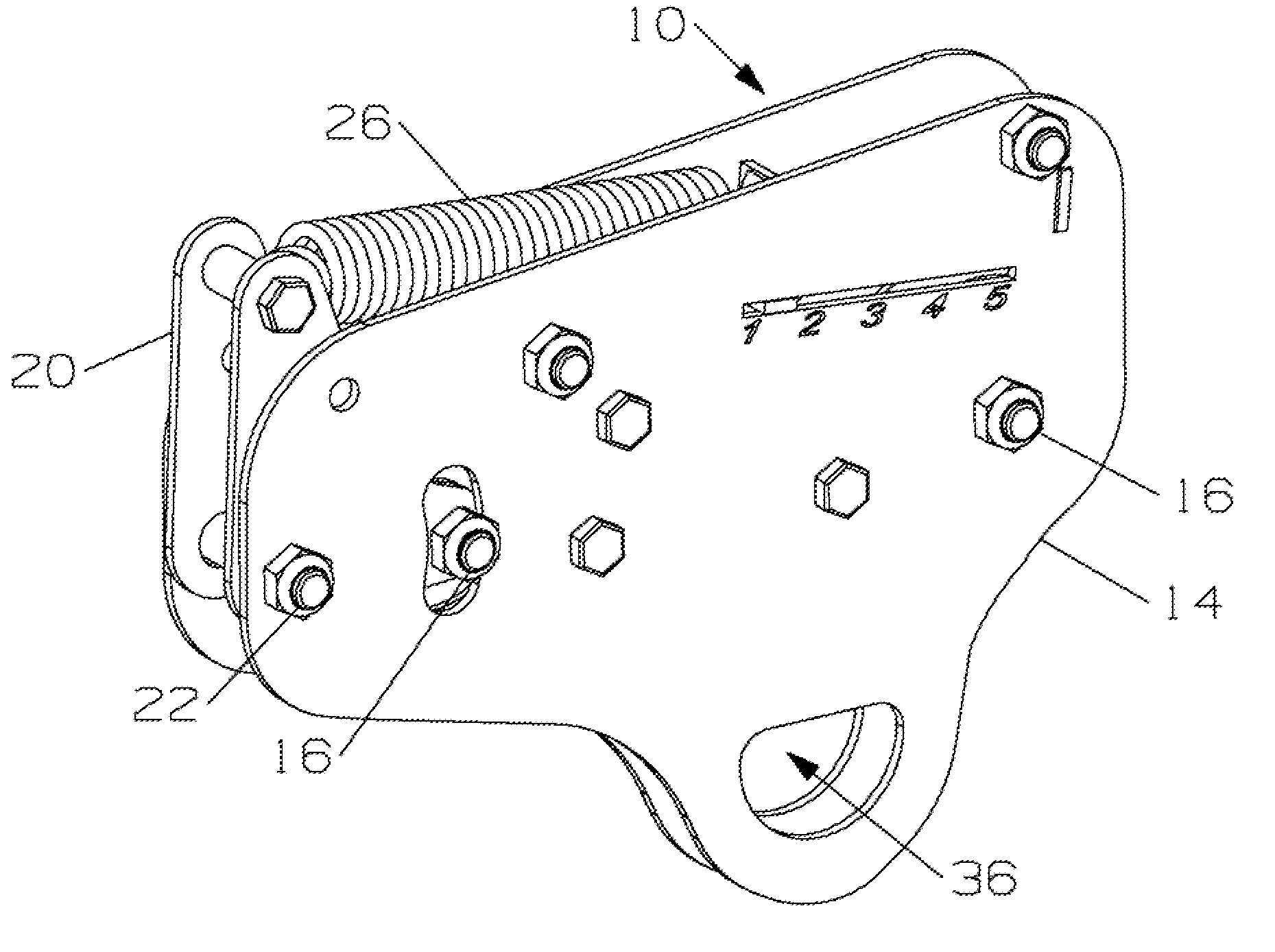
[0006]As can be appreciated by one of ordinary skill in the art, as the slope of the cable transitions from downward to upward, the greater the displacement of rider's weight away from the fixed pulley and toward the friction shoe, thus, increasing the braking force generated against the cable.
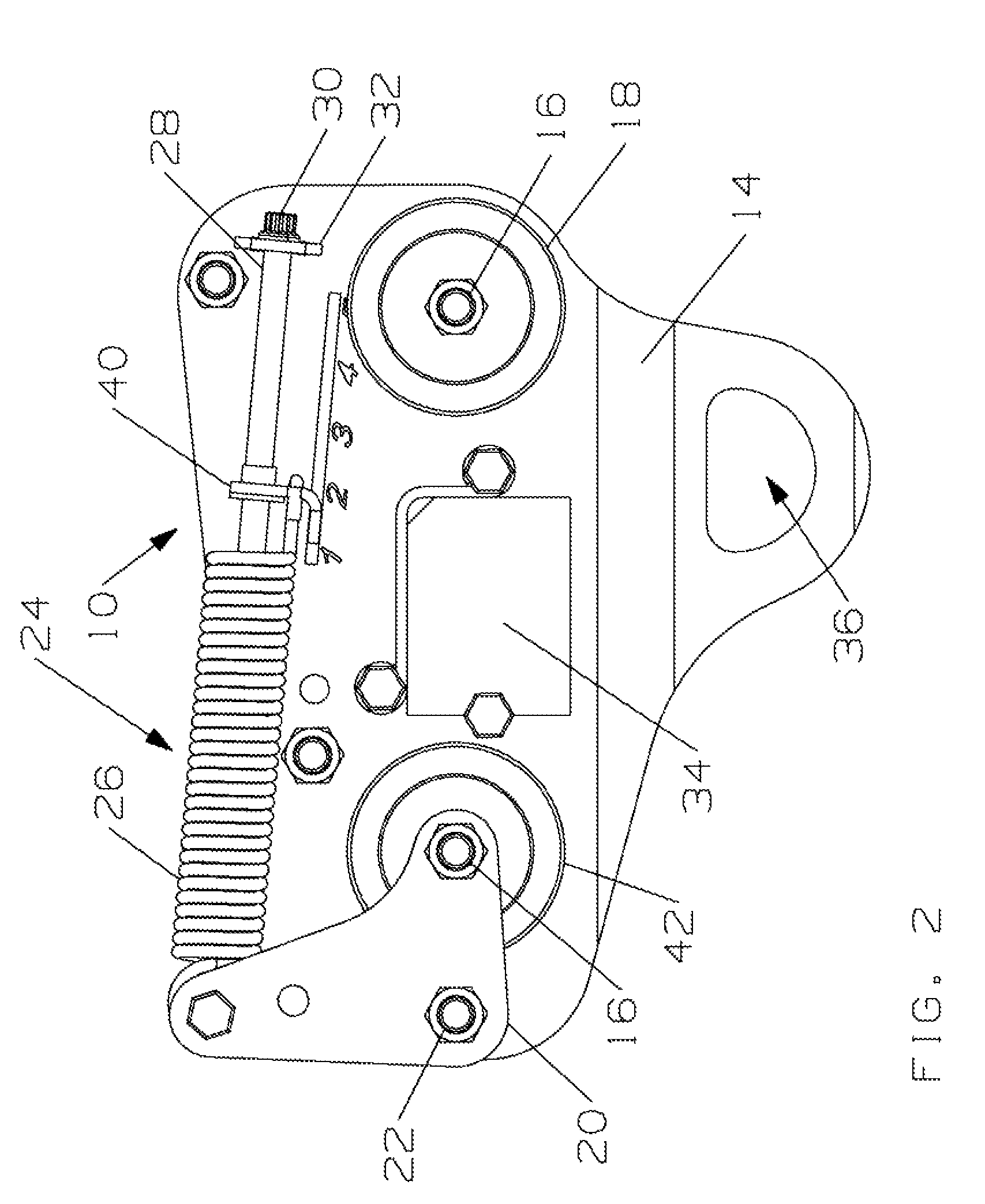
[0007]Accordingly, by adjusting the tension of the spring which forces the floating pulley against the cable, a user may control, within a particular range, the amount of braking force generated for a particular rider's weight and cable slope.
[0008]If a higher speed is desired, the spring tension bias force on the pulley may be increased. In this case, the bias spring forces the floating pulley against the cable, thus reducing the force of the friction shoe against the upper surface of the cable, resulting in lesser braking force.

Problems solved by technology

Often a material that has certain advantageous characteristics may have others that are disadvantageous.
Accordingly, the material may be suitable for dry conditions, yet be hazardous for wet conditions.

Method used


Image

  • Trolley braking system
  • Trolley braking system
  • Trolley braking system

Examples


Embodiment Construction

[0018]It will be readily understood that the components of the present invention, as generally described and illustrated in the drawings herein, could be arranged and designed in a wide variety of different configurations. Thus, the following more detailed description of the embodiments of the system and method of the present invention, as represented in the drawings, is not intended to limit the scope of the invention, as claimed, but is merely representative of various embodiments of the invention. The illustrated embodiments of the invention will be best understood by reference to the drawings, wherein like parts are designated by like numerals throughout.

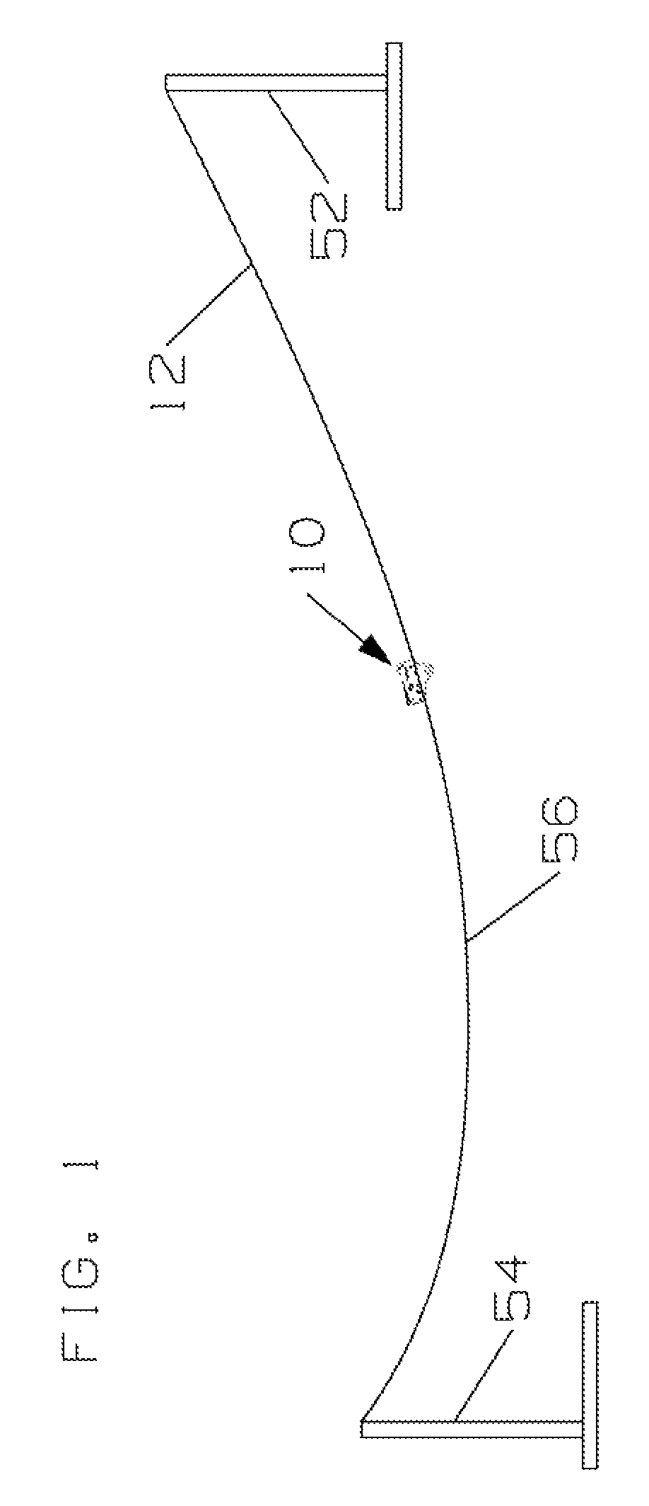
[0019]While a suspended cable may provide the basis for an amusement ride, other uses are also contemplated, including ski lifts, gondolas, aerial trams, suspended cable evacuation systems, such as oil derrick evacuation systems.

[0020]Referring to FIG. 1, a trolley 10 in accordance with the present invention may be configured fo...


PUM


Abstract

An apparatus for transporting a rider between two points on a cable or rope, having a plurality of supports configured to suspend the cable or rope between two points of unequal elevation and a trolley for transporting the rider supported by a harness on the cable or rope, the trolley having a mounting plate configured with a connection point to receive the rider's harness, a pulley rotatably mounted to the mounting plate to support the plate on the cable or rope, and a friction shoe mounted on the plate forward of the pulley to contact the upper portion of the cable or rope, wherein the connection point is located beneath the cable or rope between the centers of the pulley and the friction shoe.

Description

THE FIELD OF THE INVENTION[0001]The present invention is directed to a method and device for transporting at least one person along a suspended cable, and more particularly to a system and method for providing braking on trolleys traveling on suspended cable systems.THE BACKGROUND ART[0002]Many prior art braking devices used on trolleys configured to roll along suspended cables result in a speed that varies significantly with the slope of the cable. Accordingly, a trolley brake that provides braking force commensurate with the slope of the cable would be desirable as it would allow uninhibited downhill travel, yet would provide the necessary speed reduction when the slope of the cable increases uphill as the rider approaches the landing point.BRIEF SUMMARY OF THE INVENTION[0003]In view of the foregoing, in accordance with the invention as embodied and broadly described herein, a method and apparatus are disclosed for a trolley which provides braking force commensurate with the slope...

Claims


Application Information

Patent Timeline
Patent Type & Authority Patents(United States)
IPC IPC(8): B61B7/00
CPCB61H9/02F16D63/008A63G21/22
Inventor BOREN, DANIEL BLAIREPSTEIN, BRETT J.HAAS, JOEL C.HICKMAN, JASON B.PRUS, GARY P.LOVINGER, DAVID J. W.WILSON, JR., JAMES R.
Owner ADVENTURE HLDG
Why Eureka
Try Eureka