
Pneumatic tire

a pneumatic tire and tire body technology, applied in the field of pneumatic tires, can solve the problems of increasing road noise and greatly deteriorating ride comfort, and achieve the effects of suppressing local bending deformation, improving pinch cut resistance, and suppressing the increase of tire rigidity

Inactive Publication Date: 2012-08-07
SUMITOMO RUBBER IND LTD
View PDF8 Cites 2 Cited by
  • Summary
  • Abstract
  • Description
  • Claims
  • Application Information

AI Technical Summary

Benefits of technology

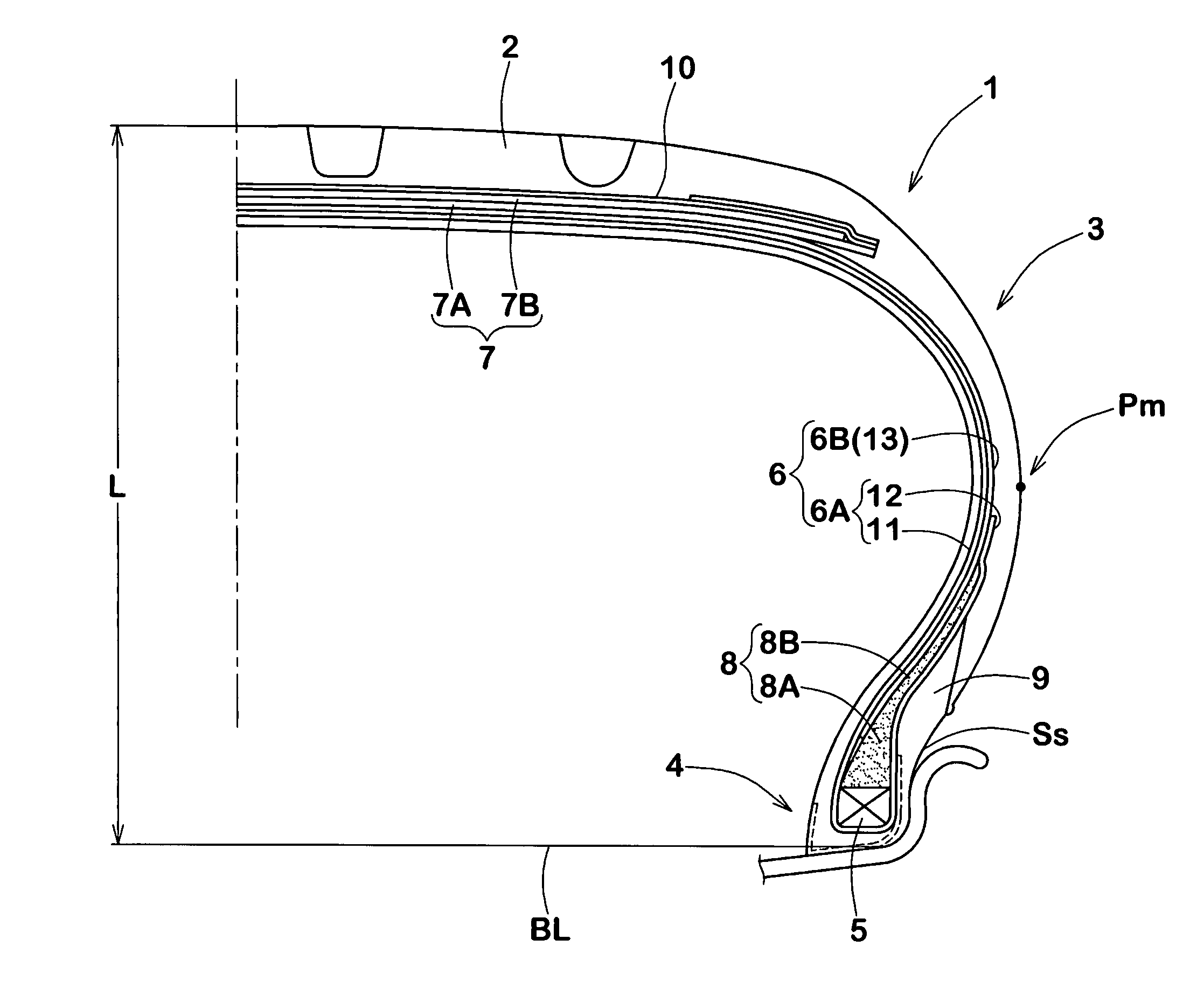
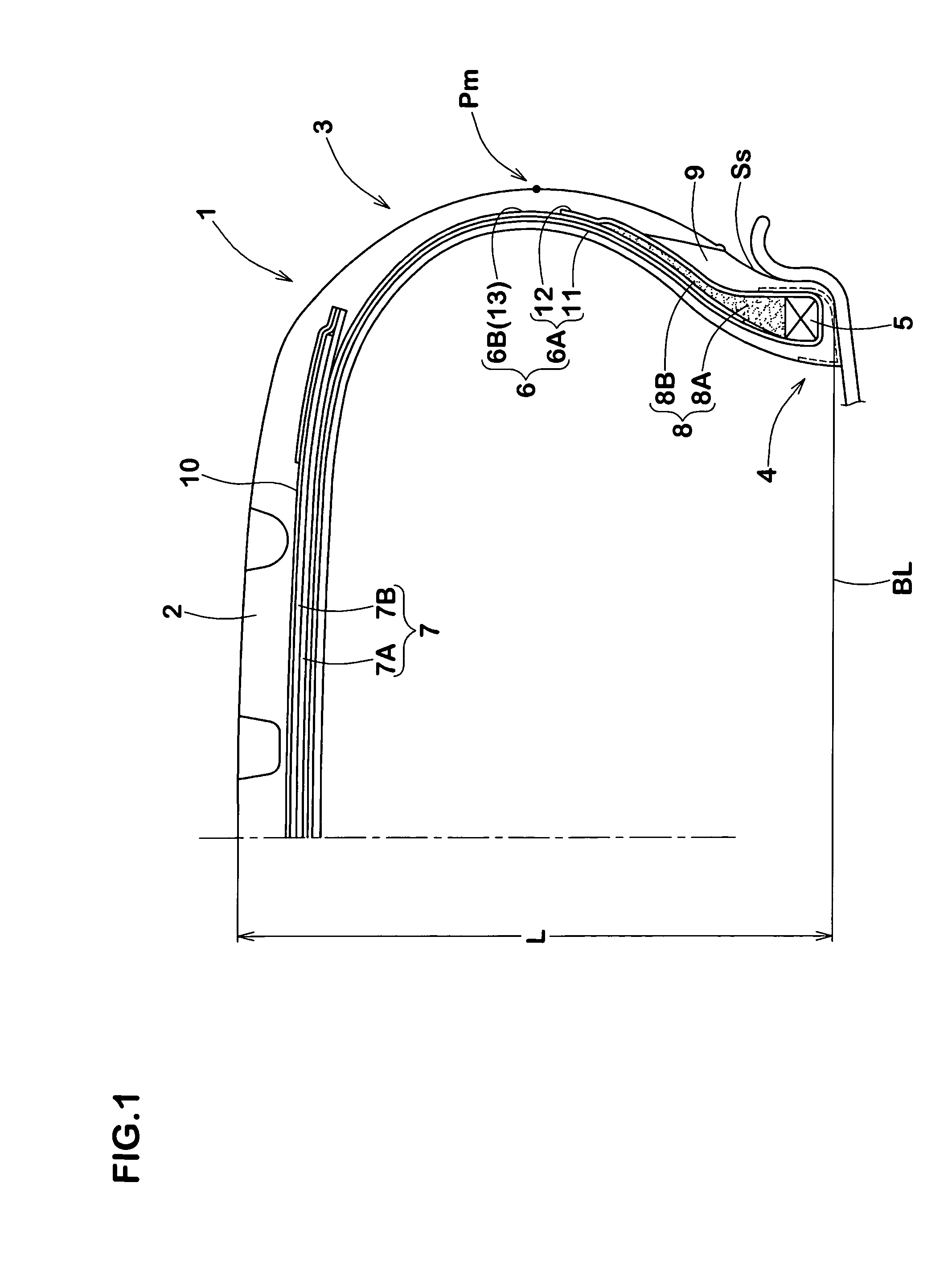
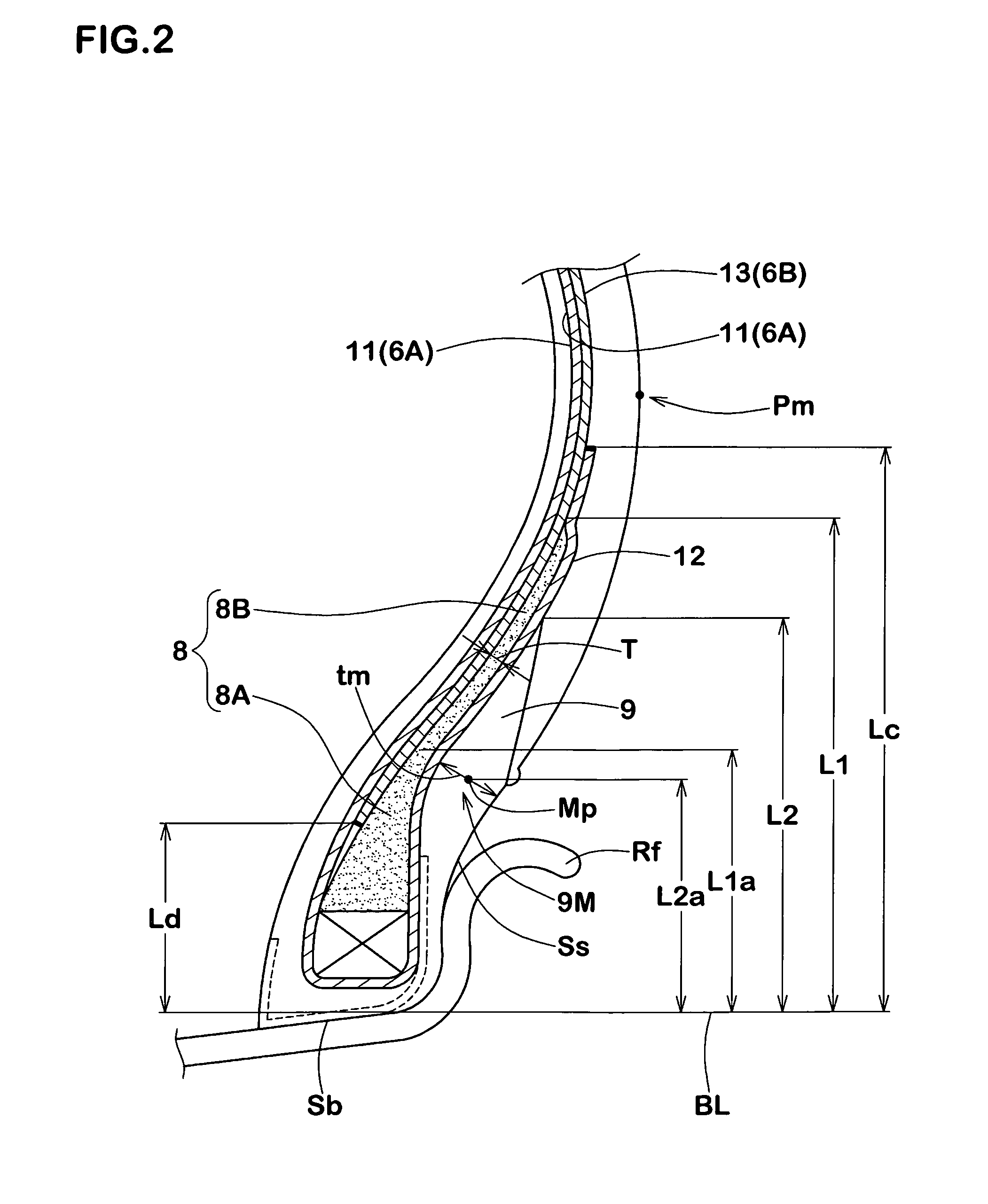
[0014]Since the present invention is constructed as mentioned above, a neighborhood of a tire maximum width position at which the deflection is maximum and pinch cut is easy to occur, can be reinforced by two carcass plies to suppress local bending deformation, whereby the pinch cut resistance can be improved. Further, since the outer carcass ply is composed of only a body portion and is superposed on a body portion of the inner carcass ply, increase of the tire rigidity can be suppressed as small as possible. Furthermore, since the bending center in deformation of bead is shifted toward the carcass side by appropriateness of balance in hardness between the bead apex rubber and the clinch rubber and, also, in cooperation with that the turnup height Lc of the inner carcass ply is held 60% or less of the section height L of the tire, the increase of the tire rigidity can be further suppressed, so it is possible to suppress deterioration of ride comfortability and noise performance.

Problems solved by technology

However, this manner has a problem that the ride comfortability is greatly deteriorated since the tire rigidity is greatly increased as compared with a carcass formed of a single carcass ply.
Further, there arises a problem that a road noise increases since a resonance frequency in the circumferential direction of tire increases.

Method used


Image

  • Pneumatic tire
  • Pneumatic tire
  • Pneumatic tire

Examples


examples

[0049]Low aspect ratio tires for passenger cars having a tire size of 225 / 45R17 and having the structure shown in FIG. 1 were manufactured based on the specifications shown in Table 1, and tested with respect to vertical spring, lateral spring, steering stability, ride comfortability, noise performance, and pinch cut resistance. The results are shown in Table 1.

(1) Lateral Spring and Vertical Spring

[0050]A vertical load of 4.1 kN was applied to a tire mounted on a rim (17×8JJ) and inflated to an inner pressure of 230 kPa, and the vertical deflection was measured. The vertical spring constant was obtained by dividing the vertical load by the vertical deflection. Also, a vertical load of 4.1 kN and a lateral force of 2.0 kN were applied to the tire, and the lateral deflection of the tire was measured. The lateral spring constant was obtained by dividing the lateral force by the lateral deflection. The spring constants are shown as an index based on the results of Conventional Example ...


PUM


Abstract

A pneumatic tire including bead apex rubbers 8 having a rubber hardness Hs1 of 80 to 95 and extending radially outward from bead cores 5, and clinch rubbers 9 having a rubber hardness Hs2 of 65 to 85 lower than the rubber hardness Hs1 and forming outer surfaces of bead portions. A carcass 6 is formed of an inner carcass ply 6A comprising a body portion 11 extending between bead cores 5, 5 and turnup portions 12 which are continuous with the body portion 11 and are turned up around the bead cores 5, and an outer carcass ply 6B comprising a body portion 13 which extends along the outer surface of the body portion 11, and the radially inner ends of which are sandwiched between the body portion 11 and the bead apex rubbers 8 to terminate there. The turnup height Lc of the turnup portion 12 from the bead base line BL is 60% or less of the tire section height L, and the height Ld of inner ends of the body portion 13 is 60% or less of the height L1 of the bead apex rubber 8.

Description

TECHNICAL FIELD[0001]The present invention relates to a pneumatic tire capable of exhibiting an excellent pinch cut resistance while suppressing deterioration of ride comfortability and noise performance.BACKGROUND ART[0002]With development of high speed vehicles and high performance vehicles, development of pneumatic tires having a low aspect ratio has been promoted and, in recent years, low aspect ratio tires having an aspect ratio of 50% or less have also been popularly used. However, in case of low aspect ratio tires, since the radial height of the sidewall portions thereof is small, the sidewall portions are greatly deformed so as to be sandwiched between a road and a rim flange when the tire falls into a large depression in a road or runs onto a projection such as curbstone on a road. Thus, tire damages such as cutting of carcass cords or separation of carcass cords from a rubber, i.e., so-called pinch cut, are easy to occur owing to bending occurring locally at the time of th...

Claims


Application Information

Patent Timeline
Patent Type & Authority Patents(United States)
IPC IPC(8): B60C15/00B60C15/06
CPCB60C15/0018B60C15/06Y10T152/10828Y10T152/10819B60C2015/0614B60C2015/009B60C15/00
Inventor KUNIYASU, YASUAKI
Owner SUMITOMO RUBBER IND LTD
Learn More