Compliant joint

a technology of compliant joints and joints, applied in the direction of couplings, slip couplings, manufacturing tools, etc., can solve the problems of limited safety, unexpected accident of people, and collision of intellectual service robots with unexpected obstacles, so as to achieve simple and strong structure and maintain rigidity

Active Publication Date: 2012-08-07
SAMSUNG ELECTRONICS CO LTD
View PDF11 Cites 6 Cited by
  • Summary
  • Abstract
  • Description
  • Claims
  • Application Information

AI Technical Summary

Benefits of technology

[0012]Accordingly, it is an aspect of the present invention to provide a compliant joint, which has a simple and strong structure and achieves passive compliance of a robot such that the compliant joint can provide flexibility to the robot when external force greater than a designated value is applied, and allows the robot to maintain rigidity when external force below the designated value is applied.
[0023]Each of the cam guide units may include a stopper restricting the movement of a corresponding one of the rollers, so that the rotation of the cam may be restricted and thus the rotation of the rotating member may be restricted.

Problems solved by technology

However, the intellectual service robots may collide with an unexpected obstacle while carrying out operations.
That is, the intellectual service robots may collide with a person and apply an impact upon the person, thus generating an unexpected accident to the person.
The active method uses the sensor and controls the feedback signal, thus being limited in achieving safety.
For example, when a vision sensor is used, the vision sensor has a low resolving power, and thus cannot promptly cope with external impact when the external impact is applied to the vision sensor at a high speed.
Further, when noise is mixed with a signal of the sensor and external impact greater than a controllable bandwidth is applied, the vision sensor cannot cope with this situation.
However, the passive method does not use a special sensor and absorbs impact through a mechanical mechanism, thus having a high reaction velocity and no danger of errors.
The safety unit uses multiple links and thus has a complicated structure, and is weak when load in the perpendicular direction of a plane, on which the multiple links are operated, is applied.

Method used


Image

  • Compliant joint
  • Compliant joint
  • Compliant joint

Examples


Embodiment Construction

[0041]Reference will now be made in detail to the embodiments, examples of which are illustrated in the accompanying drawings, wherein like reference numerals refer to like elements throughout. The embodiments are described below to explain the present invention by referring to the figures.

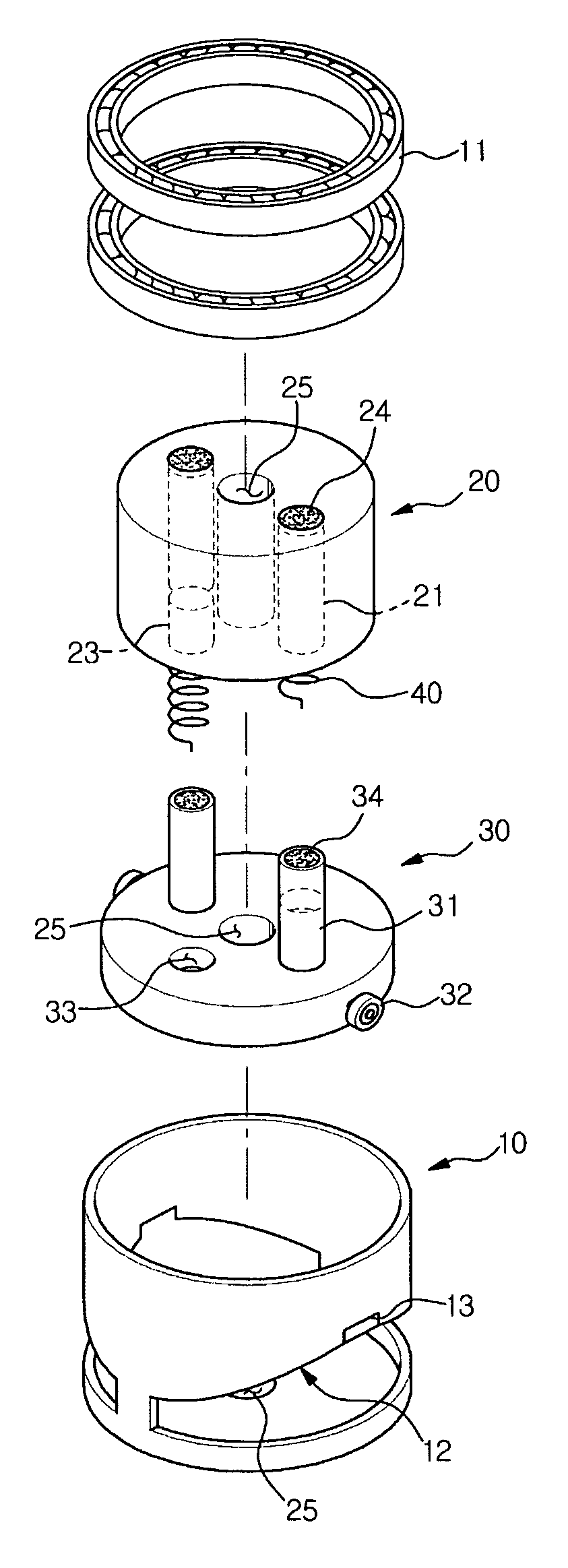
[0042]FIG. 1 is a plan view of a compliant joint in accordance with the embodiments of the present invention.

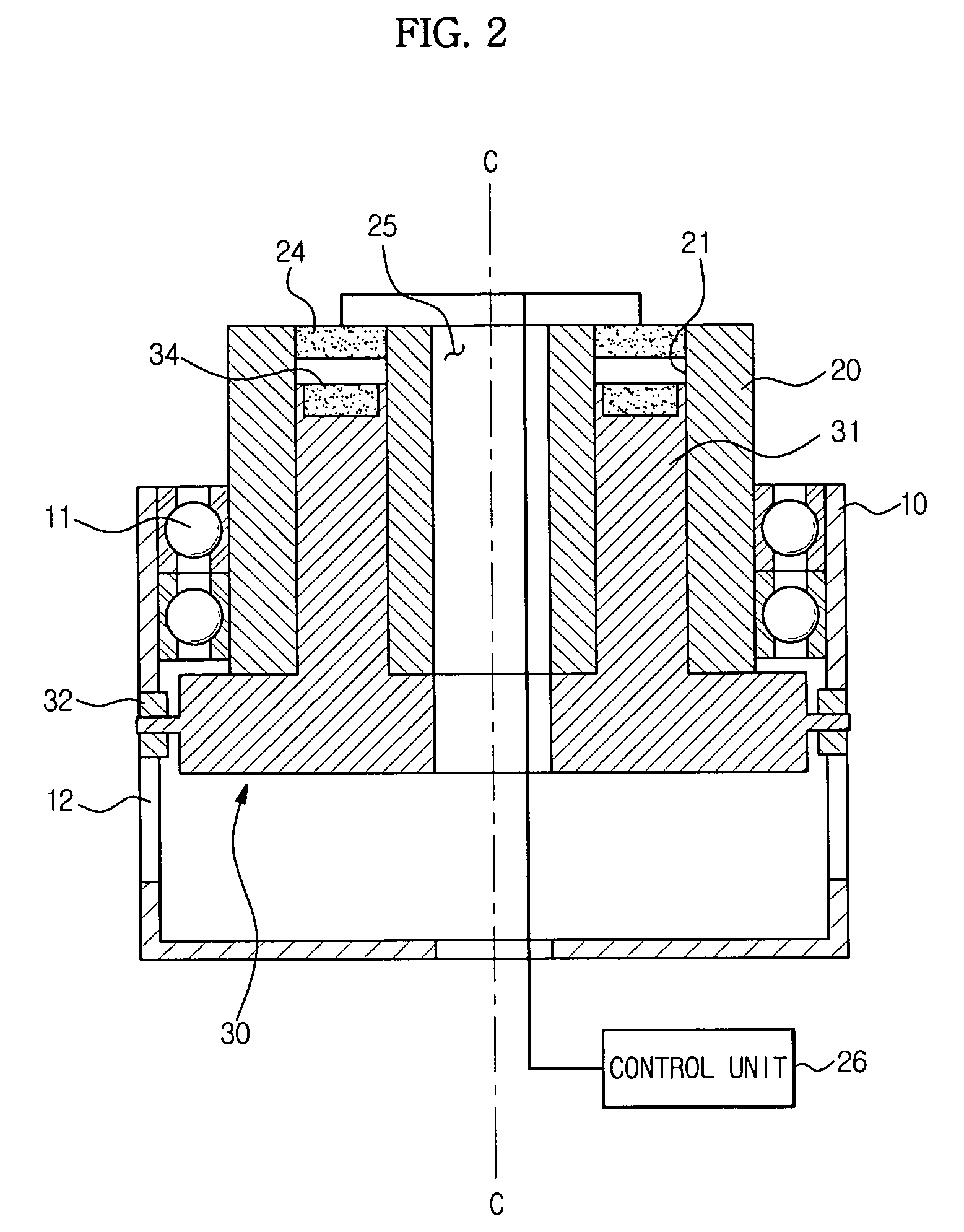
[0043]As shown in FIG. 1, the compliant joint includes a housing 10 having a loop-shaped cross section, and a rotating member 20 rotatably installed in the housing 10. Bearings 11 are installed between the inner surface of the housing 10 and the outer surface of the rotating member 20 such that the housing 10 and the rotating member 20 can be mutually rotated. Further, a cam 30 is installed between the housing 10 and the rotating member 20, and thus connects the housing 10 and the rotating member 20 so as to limit the mutual rotation of the housing 10 and the rotating member 20 and removes ...


PUM


Abstract

Disclosed is a compliant joint achieving passive compliance. The compliant joint includes a housing and a rotating member mutually rotatably provided; and a cam provided between the housing and the rotating member, and connected to the housing and the rotating member respectively. The cam is connected to the rotating member to rotate together with the rotation of the rotating member, or be independent of the rotating member so as to move in the axial direction of the rotating member separately from the rotating member. The cam is connected to the housing such that the cam can maintain the connection with the housing when external force below a designated value is applied to the rotating member, and release the connection with the housing in the case that external force more than the designated value is applied to the rotating member.

Description

CROSS-REFERENCE TO RELATED APPLICATIONS[0001]This application claims the benefit of Korean Patent Application No. 2008-0023652, filed Mar. 14, 2008, in the Korean Intellectual Property Office, the disclosure of which is incorporated herein-by reference.BACKGROUND[0002]1. Field[0003]The present invention relates to a compliant joint, and more particularly, to a compliant joint, which provides flexibility to a robot when external force greater than a designated value is applied to the robot, and allows the robot to maintain rigidity when external force below the designated value is applied to the robot.[0004]2. Description of the Related Art[0005]Industrial robots have been widely used in production lines to carry out correct operations without manipulation or control by human beings. For example, a robot used in the automobile industry carries out various operations, such as carrying a frame of a vehicle or welding, without interaction with a human being.[0006]On the other hand, inte...

Claims


Application Information

Patent Timeline
Patent Type & Authority Patents(United States)
IPC IPC(8): F16D3/62
CPCB25J17/0208F16D7/044Y10T464/30B25J19/06B25J17/00
Inventor SHIM, YOUNG BOLEE, JA WOOLEE, YOUN BAEKKIM, JEONG HUNOH, YEON TAEKYANG, SOO SANGYANG, HYUN SEOKHYUN, DONG JUN
Owner SAMSUNG ELECTRONICS CO LTD
Why Eureka
Try Eureka