
Voice prosthesis, insertion tool and method

a voice prosthesis and insertion tool technology, applied in the field of voice prosthesis, can solve the problems of inability to speak, inability to achieve speech, and inability to achieve optimal efficiency, so as to reduce the possibility of complications related to voice prosthesis and improve speech quality

Active Publication Date: 2012-08-07
COLOPLAST AS
View PDF14 Cites 19 Cited by
  • Summary
  • Abstract
  • Description
  • Claims
  • Application Information

AI Technical Summary

Benefits of technology

Enhances speech quality by increasing inner diameter while maintaining a small outer diameter, simplifies the insertion process, and minimizes complications and leakage issues.

Problems solved by technology

Due to these measures the ability to speak is lost.
However, a device of this type has a relatively small inner diameter in relation to the outer diameter, so that it from an efficiency point of view is not optimal.
Therefore, the voice prosthesis disclosed in U.S. Pat. No. 5,314,470 does not have an optimal ratio between maximal outer diameter of the through passage and the smallest inner diameter of the voice prosthesis.
During this procedure, there is a risk, especially when the user performs the removal or insertion of the prosthesis, that the prosthesis is dropped into the oesophagus, which is less dangerous as the prosthesis most often passes the intestines without problem, or into the trachea, which may be a major problem for the user.
However, one problem related with these straps is frequent leakage of respiratory gases passing under or beneath the tape.
Another problem is that insertion of the prosthesis, which often is done by means of an insertion tool onto which the prosthesis is releasably attached, is cumbersome for the user, since the user has to control both the positioning of the prosthesis in the fistula and the strap requiring the use of two hands, see for example U.S. Pat. No. 5,064,433.

Method used


Image

  • Voice prosthesis, insertion tool and method
  • Voice prosthesis, insertion tool and method
  • Voice prosthesis, insertion tool and method

Examples


Embodiment Construction

[0026]The following description focuses on a particular embodiment of the present invention. However, it will be appreciated that the invention is not limited to this embodiment.

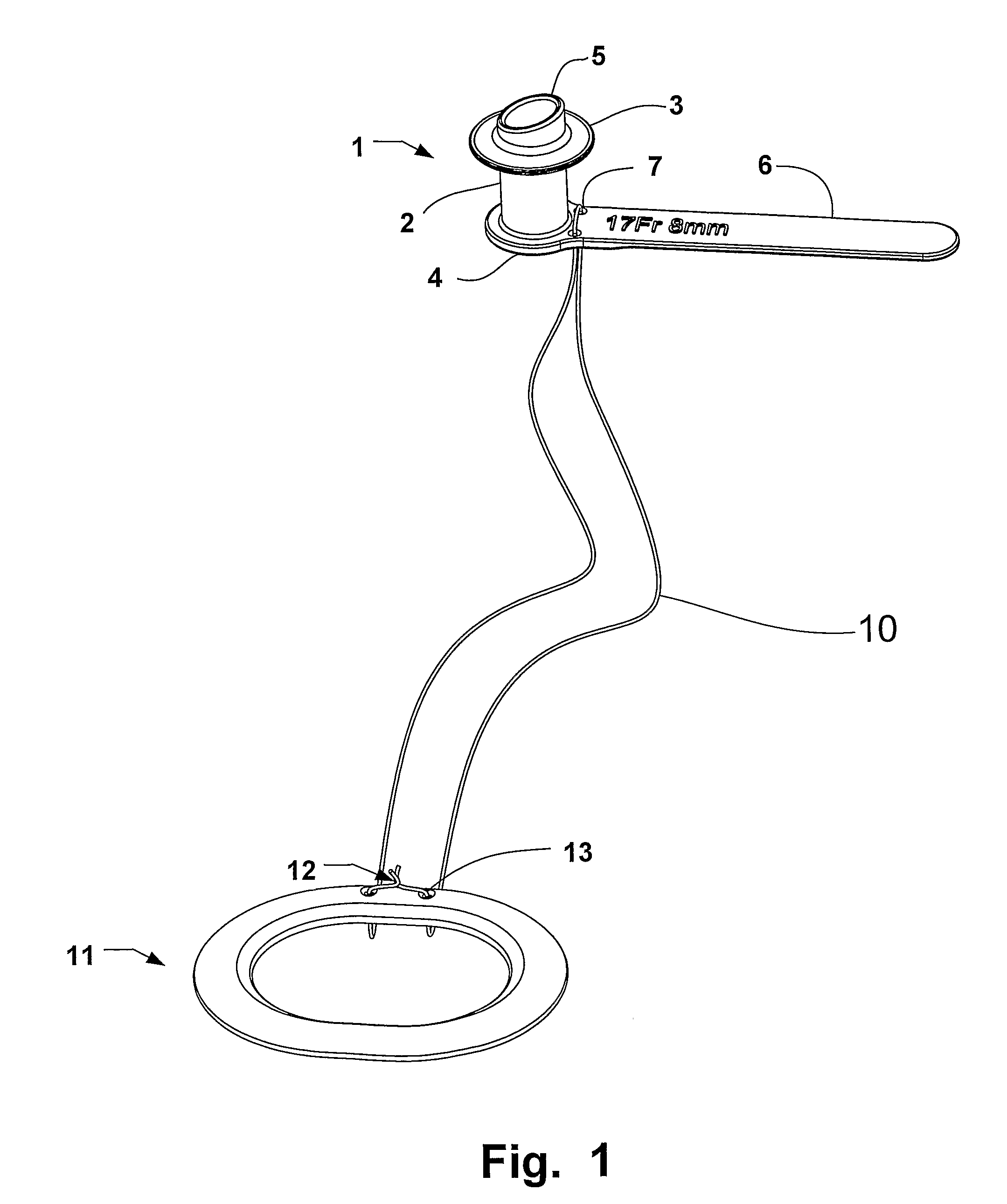
[0027]FIG. 1 is an isometric view of a voice prosthesis according to the invention. The voice prosthesis 1 comprises a tubular body portion 2, which may have a substantially cylindrical outer surface. A distal flange 3 is arranged adjacent a distal end of the tubular body portion and a proximal flange 4 is arranged adjacent the proximal end of the tubular portion. The tubular body portion extends beyond the distal flange by a distal end portion 5 as shown in FIG. 1. The end portion 5 is cut along an inclined surface in relation to the longitudinal axis of the tubular portion.

[0028]The entire voice prosthesis is made from an elastic material. The flanges are made sufficiently thin so that they may yield when the voice prosthesis is inserted by the user.

[0029]A safety strap 6 extends from the proximal flange a...


PUM


Abstract

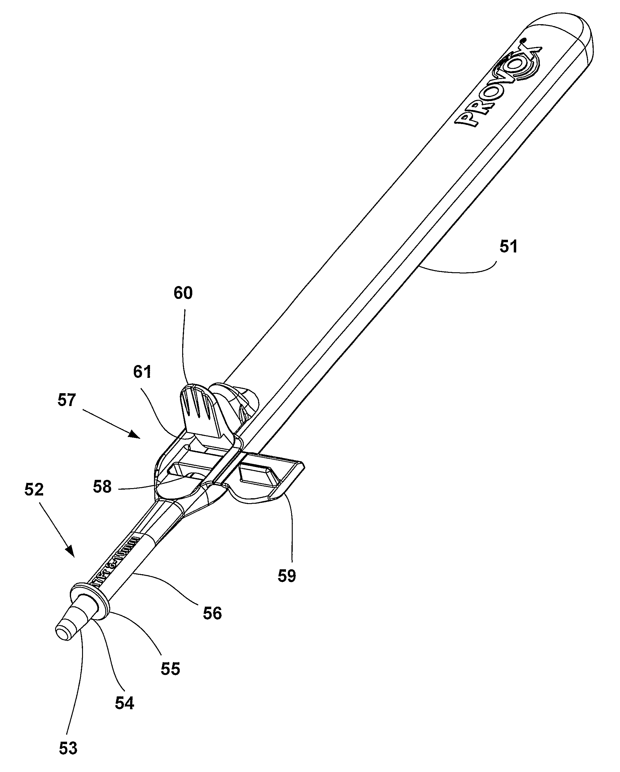
An insertion tool for inserting a tracheostoma voice prosthesis member into a fistula between oesophagus and trachea. The insertion tool includes an engagement portion for engaging and retaining said tracheostoma voice prosthesis member to be inserted into the fistula, a gripping portion for gripping a safety strap of said member in a firm grip, a shaft portion adapted to be held by one hand of a user, and a release lever arrangement adjacent said shaft portion for operation by a finger of the same hand as is holding said shaft portion, whereby said release lever, after said member being positioned in place in said fistula by operation of said insertion tool by means of said shaft, is adapted to be operated for releasing said member by one-hand operation. A tracheostoma voice prosthesis member and a method for applying said tracheostoma voice prosthesis member are also provided.

Description

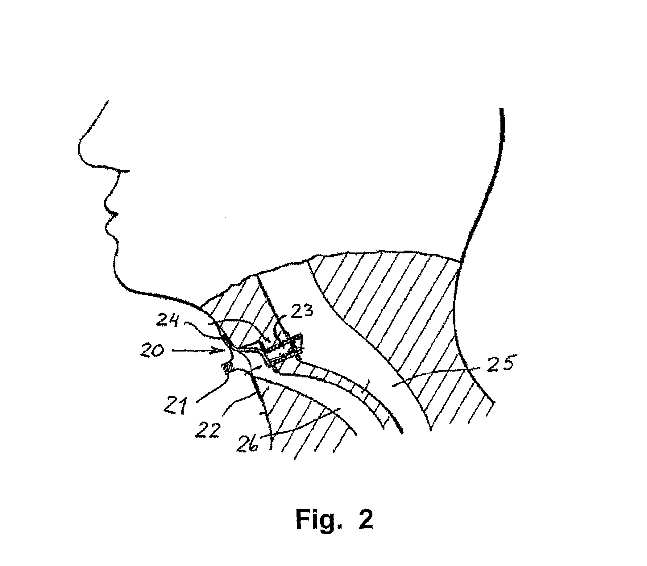
FIELD OF THE INVENTION[0001]This invention pertains to a voice prosthesis for persons whose larynx has been removed, an insertion tool for the prosthesis and a method of insertion of the voice prosthesis by means of the insertion tool.BACKGROUND OF THE INVENTION[0002]As a result of different diseases, the larynx of the diseased must sometimes be removed by surgery. The trachea is attached to the neck forming a so called tracheostoma or an artificial opening into the trachea leading out into the front portion of the neck, so as to make possible breathing. Due to these measures the ability to speak is lost.[0003]In order to restore the ability of speech to a certain extent, it is possible, by means of surgery, to open a fistula between the oesophagus and the trachea to direct air from the lungs, through the fistula and to the oral cavity. This fistula must always be closed, except when air is admitted into the pharynx, because food and liquids entering the oesophagus through the mouth...

Claims


Application Information

Patent Timeline
Patent Type & Authority Patents(United States)
IPC IPC(8): A61F11/00A61FA61F2/20
CPCA61F2/203A61F2/20
Inventor PERSSON, JAN-OVE
Owner COLOPLAST AS
Learn More