
Thermal oxidizer with gasifier

a technology of gasifier and oxidizer, which is applied in the direction of mechanical equipment, machines/engines, and combustion gas production, etc., can solve the problems of harmful environmental byproducts of manufacturing processes, and achieve the effects of cost efficiency, reducing the amount of fossil fuel, and reducing the amount of organic was

Inactive Publication Date: 2012-08-07
DURR SYST INC
View PDF21 Cites 15 Cited by
  • Summary
  • Abstract
  • Description
  • Claims
  • Application Information

AI Technical Summary

Benefits of technology

This approach significantly reduces the necessity of fossil fuel consumption and associated CO2 emissions, achieving cost efficiency and environmental benefits by minimizing unnecessary CO2 vented to the atmosphere, while enabling carbon offset tax savings.

Problems solved by technology

It is well known that manufacturing processes produce waste byproducts harmful to the environment.
However, even the RTO requires mass consumption of fossil fuel to generate the necessary BTUs to oxidize the pollutants produced by the industrial process.

Method used


Image

  • Thermal oxidizer with gasifier
  • Thermal oxidizer with gasifier
  • Thermal oxidizer with gasifier

Examples


Embodiment Construction

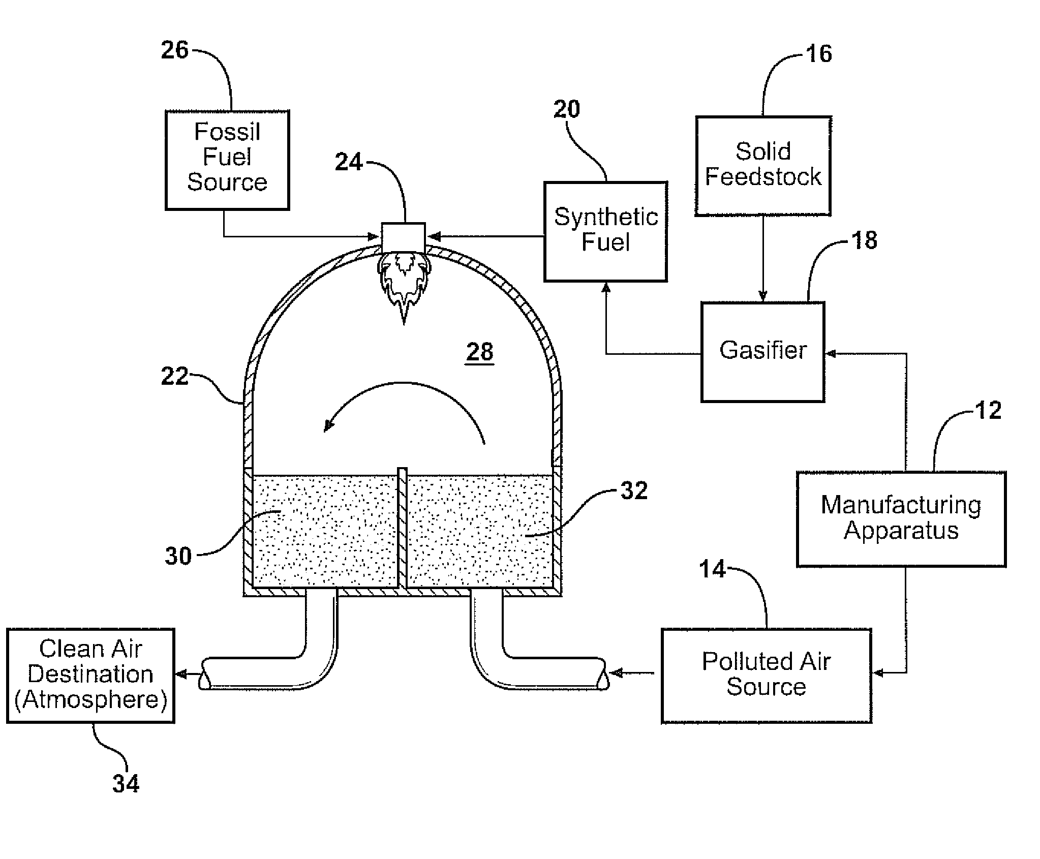
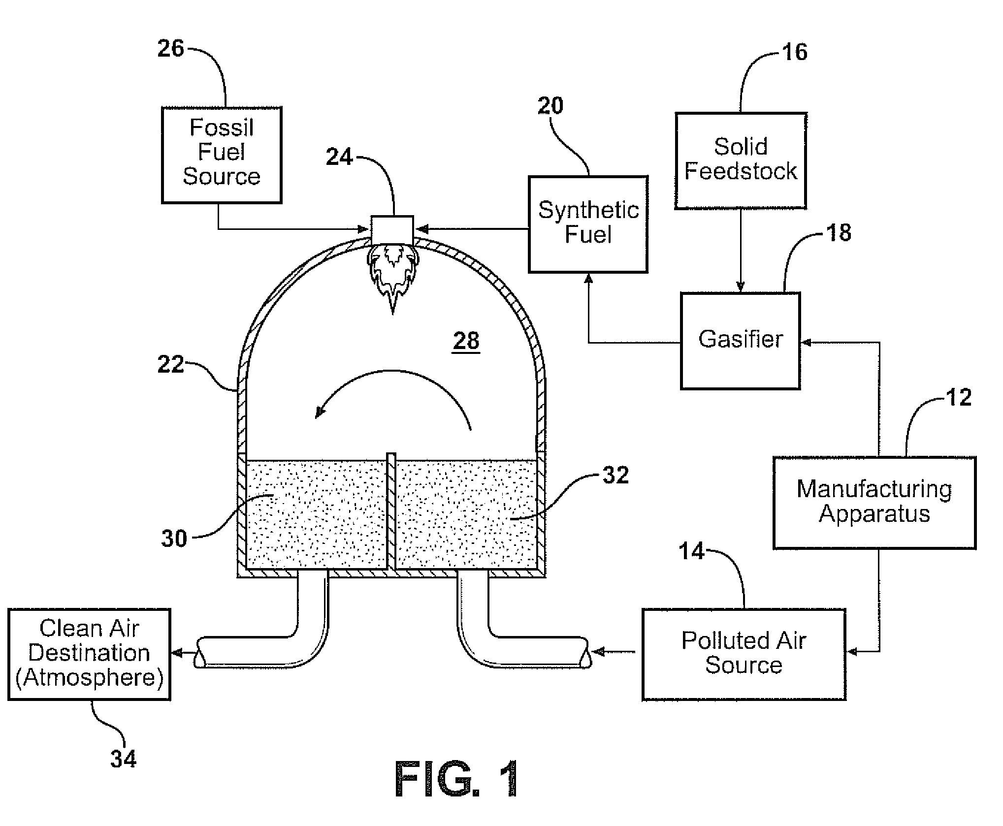
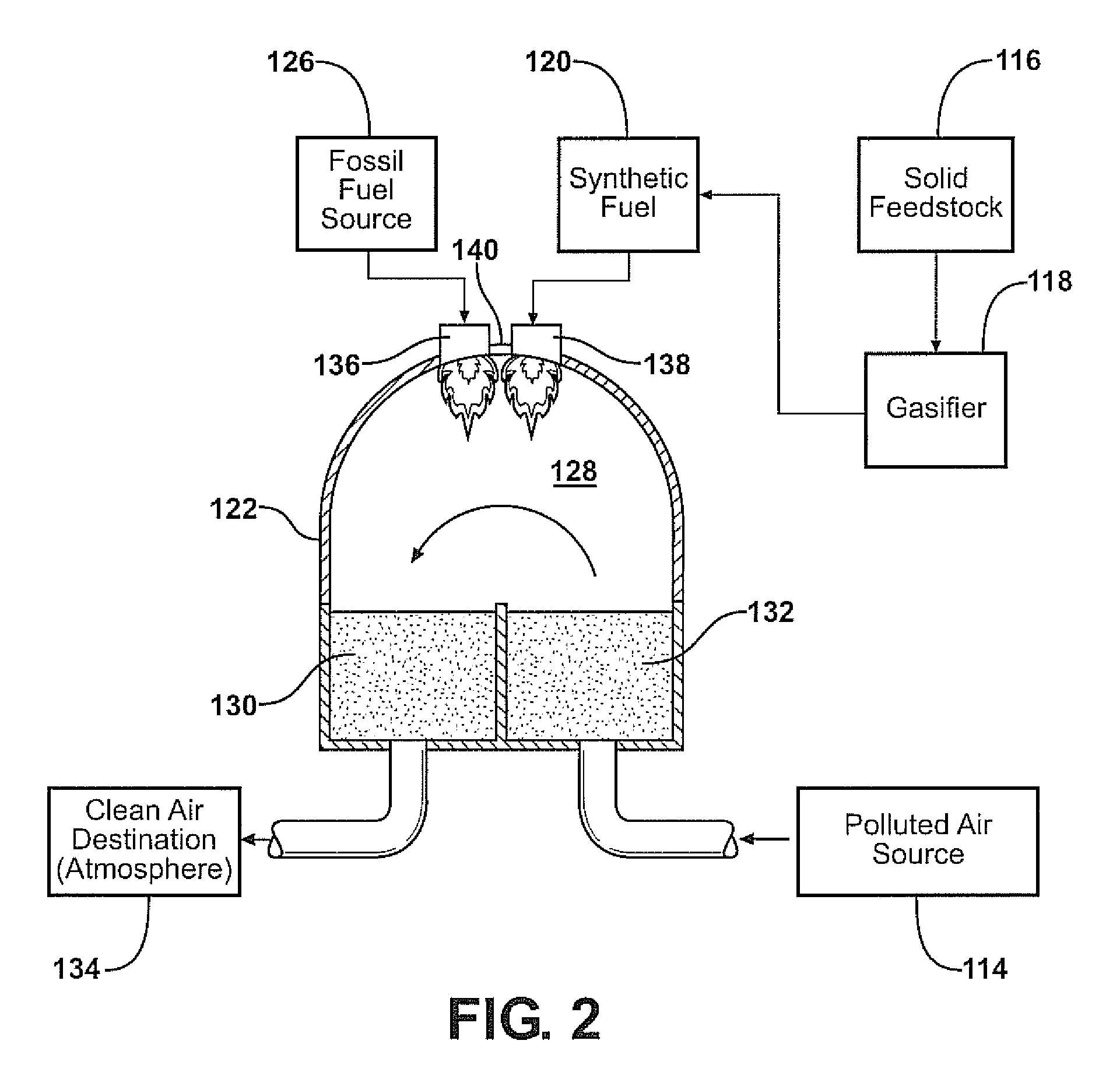
[0016]A manufacturing facility is generally shown in FIG. 1 at 10. The facility includes a manufacturing apparatus 12 that produces as a manufacturing byproduct, a polluted air source having, for example, volatile organic compound or other organic particulate matter disposed in a polluted air stream 14. One such example of the manufacturing apparatus 12 associated with the present invention is a paint application booth used for applying large volumes of industrial paint. It should be understand that the manufacturing facility 10 of the present invention could include any manufacturing process resulting in both aerosol and solid waste byproduct. For clarity, the inventive process and apparatus will be explained for use in a paint application facility throughout the specification. However, it should be understood that the solid waste byproduct used to generate synthetic gas may come from an industrial process not related to the industrial process producing polluted air stream requirin...


PUM

PropertyMeasurementUnit
energy rateaaaaaaaaaa
flow rateaaaaaaaaaa
volatileaaaaaaaaaa

Abstract

A manufacturing apparatus for producing products results in solid waste and organic waste disposed in an air stream. The organic waste is subject to oxidation by a thermal oxidizer receiving the air stream from the manufacturing apparatus for oxidizing the organic waste. The thermal oxidizer includes a clean air outlet for venting the oxidized air stream to the atmosphere. A gasifier receives solid waste from the manufacturing apparatus for gasifying the solid waste and producing synthetic gas. The synthetic gas is introduced to the thermal oxidizer for providing additional thermal energy to the thermal oxidizer reducing the amount of fossil fuel required to provide thermal energy to the thermal oxidizer that is necessary for oxidizing the organic waste disposed in said air stream.

Description

RELATED APPLICATIONS[0001]This is a non-provisional application that claims priority to a provisional application Ser. No. 61 / 032,765 filed on Feb. 29, 2008 and incorporated herewith by reference in its entirety.FIELD OF THE INVENTION[0002]The present invention is directed generally to a manufacturing apparatus having a regenerative thermal oxidizer making use of a combined gasifier. More particularly, the present invention is related to a method of reducing the amount of fossil fuel generated carbon dioxide vented to the atmosphere by operating a regenerative thermal oxidizer by reducing the amount of fossil fuel required to operate the regenerative thermal oxidizer through the addition of carbon neutral synthetic gas generated by an integrated gasifier.BACKGROUND OF THE INVENTION[0003]It is well known that manufacturing processes produce waste byproducts harmful to the environment. These waste byproducts come in various forms, including aerosol, particulate, gaseous and solids. Fo...

Claims


Application Information

Patent Timeline
Patent Type & Authority Patents(United States)
IPC IPC(8): A62D3/40B05B15/00C01B32/50
CPCC10J3/00C10J2300/0946C10J2300/095
Inventor STONE, JAMESBLOCKI, STEVEN WILLIAM
Owner DURR SYST INC
Learn More