Device for inspection of print products

a technology for printing products and devices, applied in the direction of television systems, instruments, image enhancement, etc., can solve the problems that the known zoom lenses need a rather long time for changing or switching focal widths, and achieve the effect of shortening the time for changing, reducing the time for inspection, and speeding up the check and analysis

Active Publication Date: 2012-08-07
TEXMAG GMBH VERTRIEBS
View PDF37 Cites 2 Cited by
  • Summary
  • Abstract
  • Description
  • Claims
  • Application Information

AI Technical Summary

Benefits of technology

[0010]At the picture inspection system for a printing machine according to the invention not only one single camera is directed to a particular inspections field, but there are provided at least two cameras enabling a check in the inspection field. By means of the several cameras there is particularly not only provided a system by which redundant picture information of the print product is taken or rather picked up, but the several cameras are particularly adapted to different inspection tasks. By doing so, the several cameras being provided according to the invention enable to pick up a large number of different control information out of one single same inspection field at one single view, recording or shooting moment. This can be done without shifting or moving of cameras, which—this will be explained in detail later—has a very positive effect on control times of the quality control and the reaction times during adjusting a printing process.
[0012]According to the invention it is possible to provide very quickly a picture like representation of substantially the entire area of a print product, and, at the same time, to provide a targeted quality control or rather evaluation of single details of the print product. The information can than be used for controlling and ruling of operation processes at the printing machine and of devices, which are upstream and downstream of the machine. The high speed of the check and analysis according to the invention is particularly achieved by not using zoom objectives or rather lenses along with the invention. In particular, known zoom lenses need a rather long time for changing or switching the focal width. This time can be saved by the recording technology according to the invention.
[0013]Advantageously, the device according to the invention allows the at least one further camera to be directed only to an inspection field cutout or section of the inspection field checked by the first camera. In other words, by the further camera a detail view within the inspection field of the first camera can be made by the further camera. As always several cameras are available for picture shootings, this detail view can be made simultaneously with an overview shoot. A shifting of e.g. a zoom camera is thereby not necessary. The time saved in that way enables a much quicker reaction of the operators of the printing machine if quality defects arise. Accordingly, defects can also be corrected quicker and thereby the amount of maculation at the printing machine can be reduced significantly by the invention. The lack of a zoom shifting further simplifies the control of the device according to the invention significantly, and thereby reduces the production expenses as well as the operation expenses. The cameras of the device according to the invention further basically can be arranged without moving parts, so the costs for production, maintenance and repair of the device according to the invention can be kept rather low, and in particular the production costs are usually at least not higher than those of a known camera having a respective zoom lens.
[0014]Accordingly, by the first camera of the invention it is possible to provide a visual inspection for e.g. recognizing spots, oil splashes, scraps, scratches or coating stripes. The camera provides an evaluation of faults “from a far away viewpoint”. By the second camera provided according to the invention, at the same time in particular e.g. a colorimetry, a color density measurement and / or a color register measurement is possible. In doing so, by the second camera in particular a detailed fault evaluation “from a nearby viewpoint” can be provided. The first camera may further serve for simplifying adjustment of the further camera and for simplifying locating the inspection field section on the print product. Further, the second camera may for example be used for a barcode evaluation within the inspection field used by the first camera.
[0019]For the above mentioned visual inspection by means of the device according to the invention, the device should advantageously include at least two displays or pictorial representations, in particular in form of screens, by which the inspection field checked by the first camera and the inspection field checked by the at least one further camera, which is at least partially consistent with the one of the first camera, can be displayed. Alternatively or in addition, even a single screen can be provided, on which several displays or rather representations of the inspection fields can be displayed side by side or at least partially overlapping. The observer or rather inspector may very quickly find a correlation between those two displays, and may thereby be able to judge very well the recognized faults in respect to their relevancy, as well as their basic cause.

Problems solved by technology

In particular, known zoom lenses need a rather long time for changing or switching the focal width.

Method used


Image

  • Device for inspection of print products
  • Device for inspection of print products
  • Device for inspection of print products

Examples


Embodiment Construction

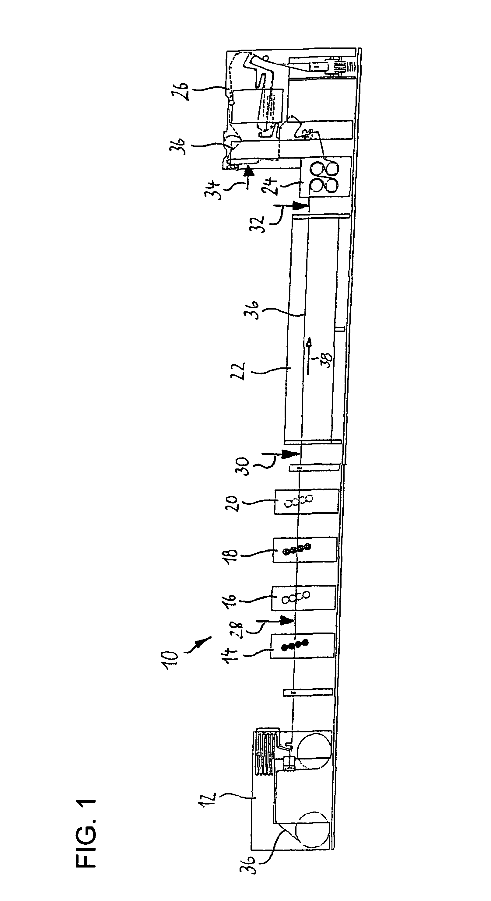
[0029]In FIG. 1 a printing machine 10 is shown which includes as essential elements a roll changer 12 with an integrated retracting unit, in total four print units 14, 16, 18 and 20, a dryer 22, a cooing unit 24 and finally a hemming apparatus including a hemming unit 26. At the printing machine 10 in total four positions for locating one or several inspection devices, which are herein also called device for inspection of print products produced by the printing machine 10 and which will be explained in further details hereinafter, are marked by means of four arrows 28, 30, 32 and 34. The inspection devices are thereby each directed to a paper web 36, which is transported in usual manner through the printing machine 10 along a transport direction 38, and which is thereby provided for example with a color print. In this way, the printing machine 10 serves e.g. as a roll offset machine for the newspaper and / or illustration printing.

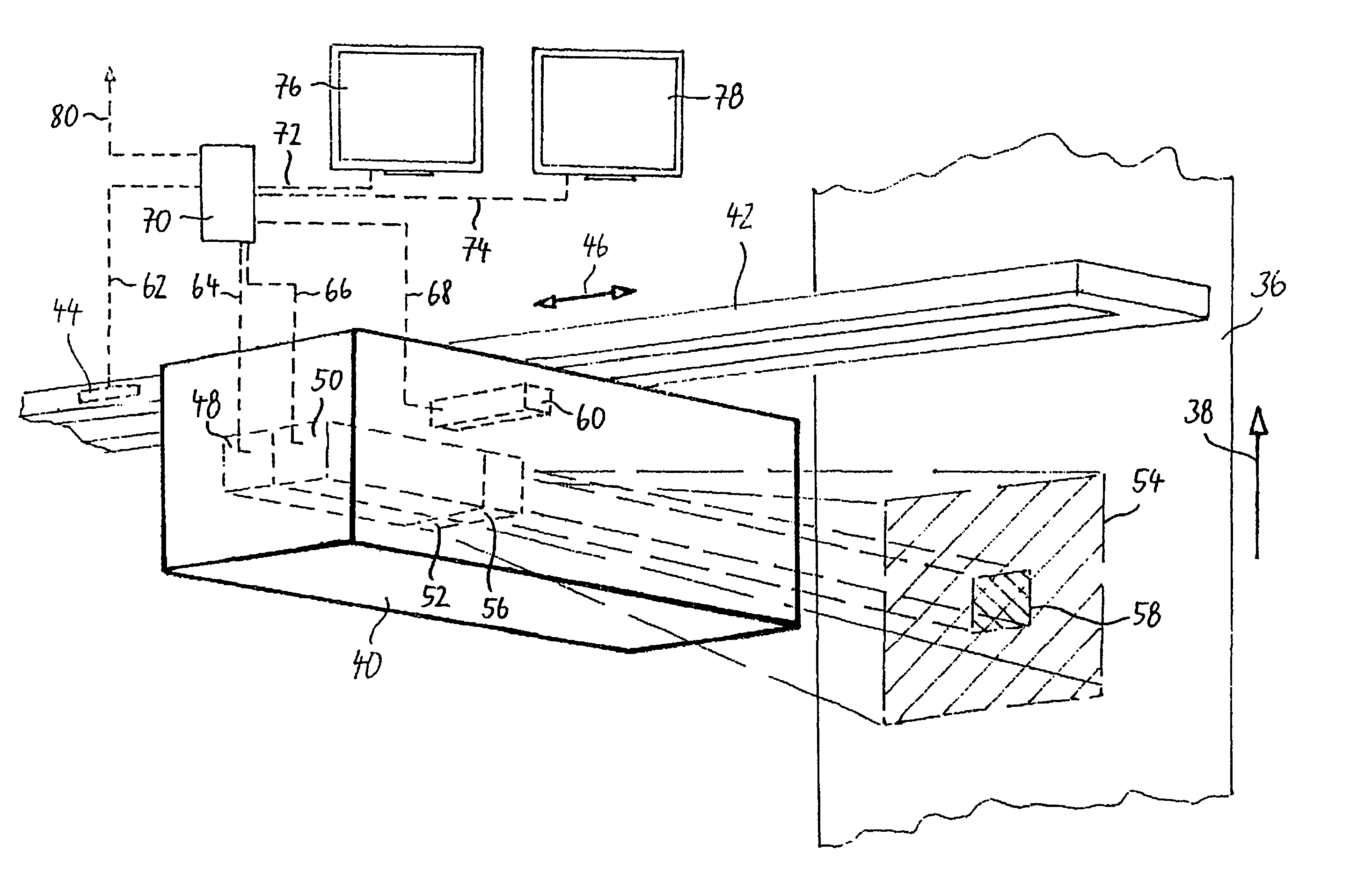
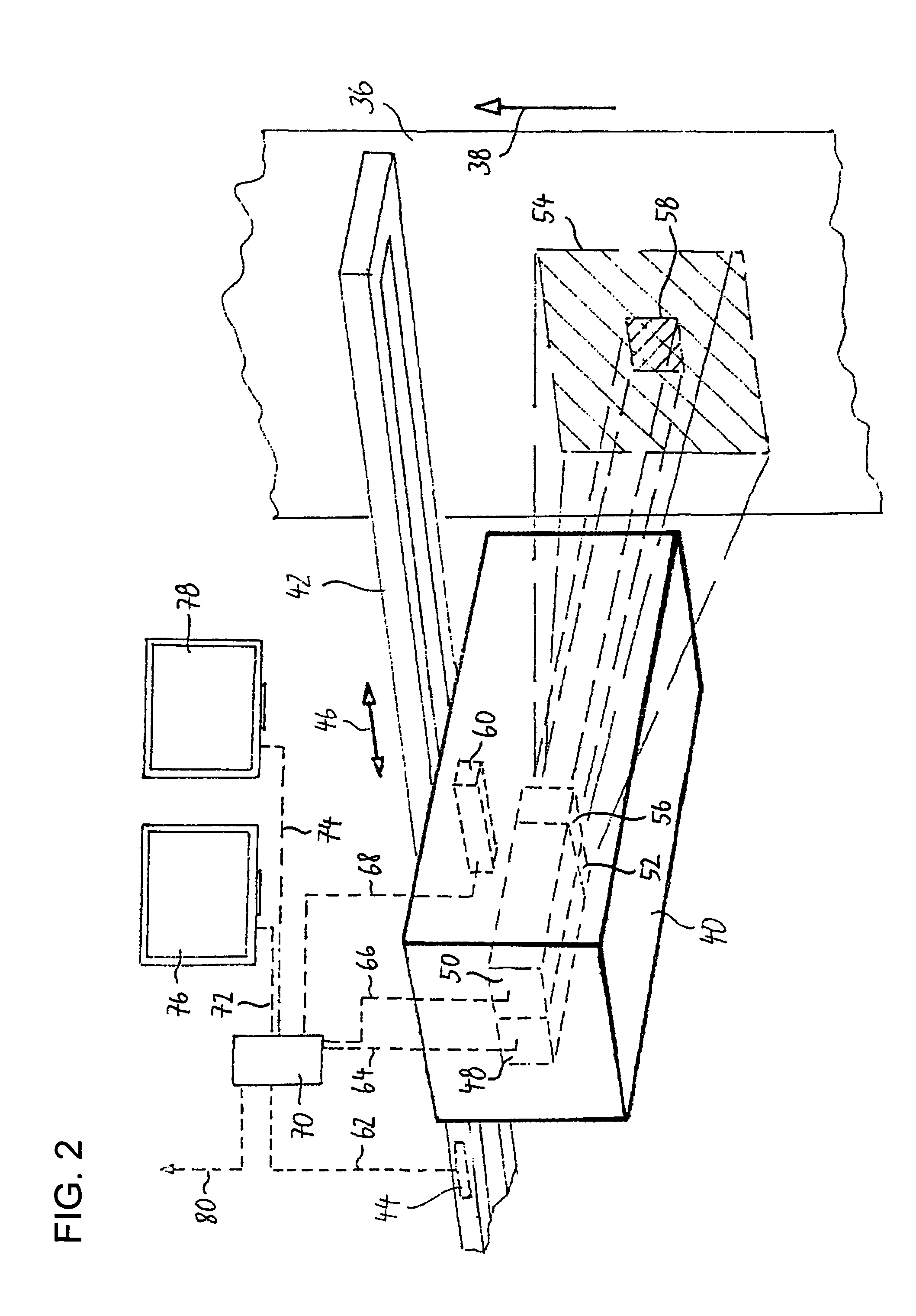
[0030]In FIG. 2 such an inspection device is shown in ...


PUM


Abstract

A device for inspection of print products (36) produced by a printing machine (10) is provided with a first camera (48) being directed to an inspection field to be checked. At least one further camera (50) is provided being directed at least partially (58) to the same inspection field (54) being checked already by the first camera (48).

Description

BACKGROUND OF THE INVENTION[0001]1. Field of the Invention[0002]This invention relates to a device in particular for inspection of print products produced by a printing machine, which is provided with a camera particularly for judging the print quality of the print products produced by the printing machine.[0003]2. Description of the Related Art[0004]Devices of the above mentioned kind are used for example with offset printing machines for detecting, if applicable after taking out a sample sheet, possible quality defects visually and / or by technical measurement, e.g. spots, scraps or scraper stripes as early as possible.[0005]Further, it is known to subject printing machines to a permanent quality control, by continuously extracting picture data with a camera and a picture recording arrangement respectively, and analyzing them manually or largely automatically. By doing so, changes of quality of the produced print products can be detected and respective warning notices can be displa...

Claims


Application Information

Patent Timeline
Patent Type & Authority Patents(United States)
IPC IPC(8): H04N9/09H04N7/18H04N7/00G06K9/00
CPCB41F33/00B41F33/0036G01N21/8903G06T7/0004H04N5/247G06T2207/20016G06T2207/30144B41F33/0081B41F33/02H04N1/6044H04N23/90
Inventor TATARCZYK, CHRISTINATATARCZYK, JOACHIM
Owner TEXMAG GMBH VERTRIEBS
Why Eureka
Try Eureka