Image forming apparatus and development cartridge in which information stored on the development cartridge can be read by the image forming apparatus
a technology of image forming apparatus and development cartridge, which is applied in the direction of electrographic process apparatus, instruments, optics, etc., to achieve the effect of improving the detachability of the development cartridge and maintaining the accuracy of reading information
- Summary
- Abstract
- Description
- Claims
- Application Information
AI Technical Summary
Benefits of technology
Problems solved by technology
Method used
Image
Examples
embodiment 1
[0017
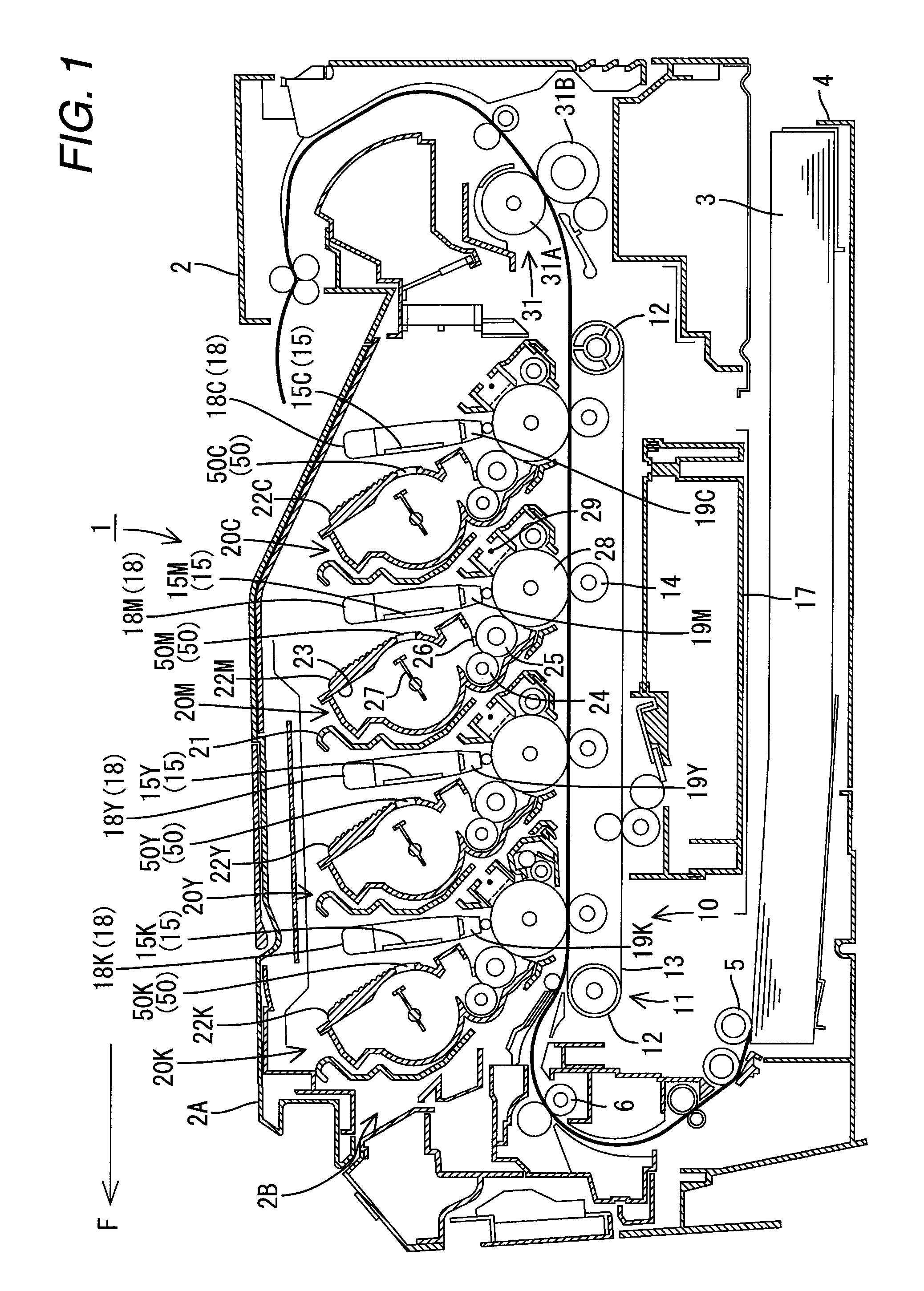
[0018]A description is given of embodiment 1 of the present invention with reference to FIG. 1 through FIG. 6.
[0019]1. Entire Configuration of Printer
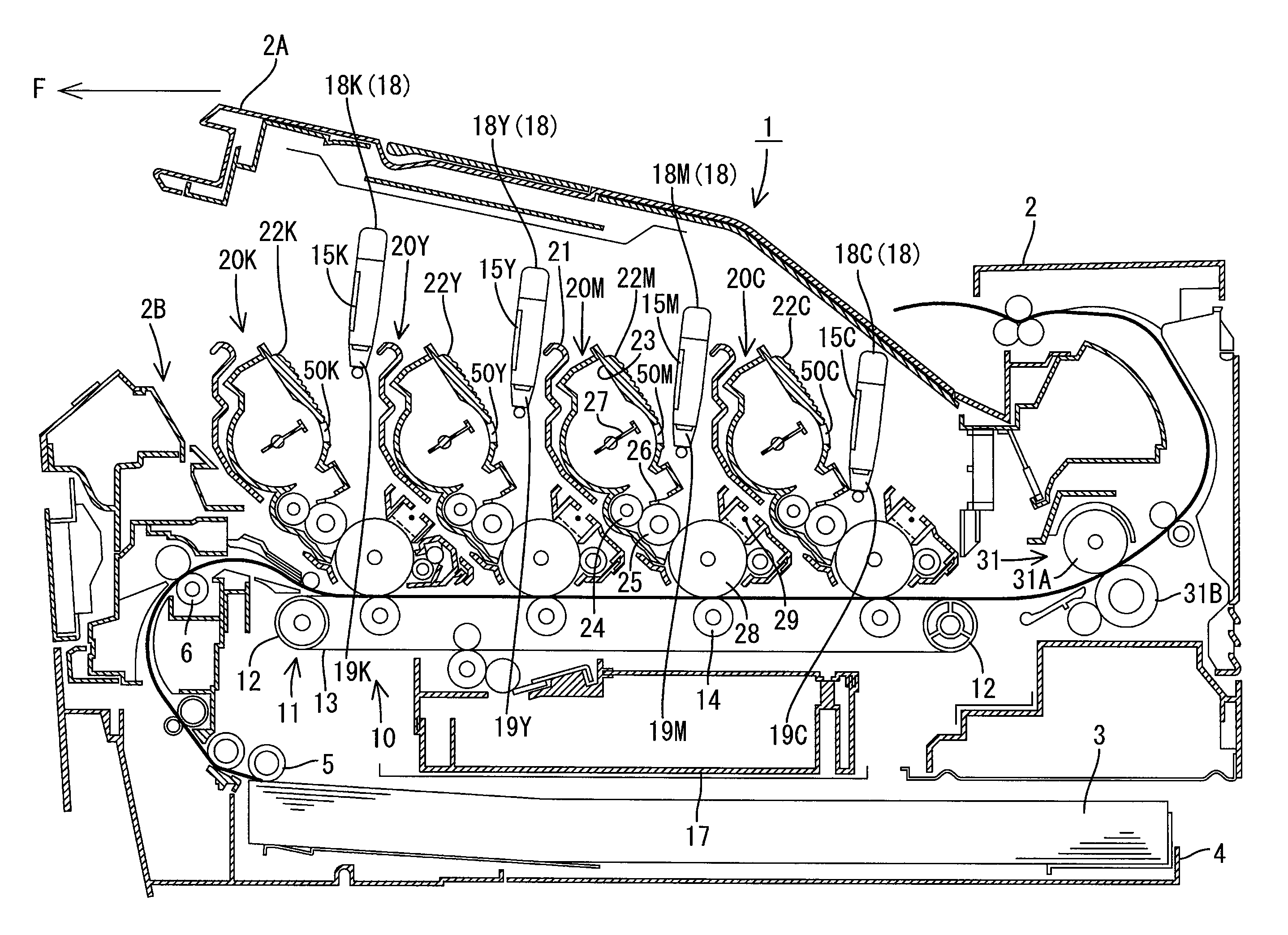
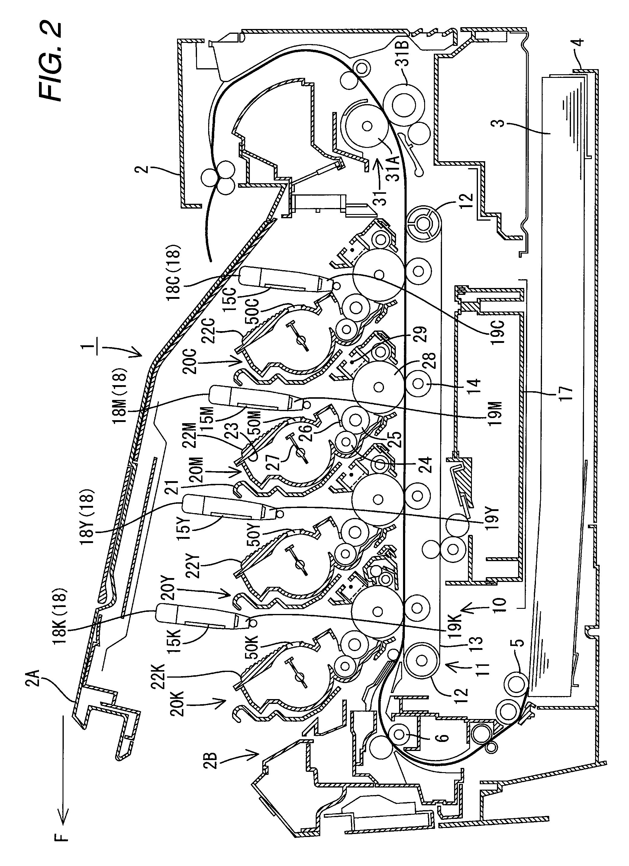
[0020]FIG. 1 and FIG. 2 are side sectional views showing a brief configuration of a printer 1 (one example of an image forming apparatus) according to the present embodiment. In the following description, the left direction of the paper of FIG. 1 andFIG. 2 is the front direction that is shown as F direction in the respective drawings. In this embodiment, the printer 1 is configured as a color printer for forming a color image by four colors of toner (black K, yellow Y, magenta M and cyan C). Hereinafter, where respective components are distinguished color by color, K (black), Y(yellow), M(magenta) and C(cyan) that signify respective colors are added to the end of reference numerals of the components. The image forming apparatus according to the present invention may be configured to use a single color (black) or five or more color...
embodiment 2
[0059
[0060]FIG. 7 shows Embodiment 2. A difference from Embodiment 1 described above resides in the location and configuration of the reader unit, and all the other portions are the same as those of Embodiment 1. Therefore, the components are given the same reference numerals, and overlapping description thereof is omitted. A description is given below of only the different points.
[0061]As shown in FIG. 7, an antenna 74 is provided on the LED-mounted substrate 71. A through hole 80 is formed at one end part of the LED-mounted substrate 71. The antenna 74 has an annular shape surrounding the through hole 80. The antenna 74 receives high frequency signals from the control circuit via a circuit pattern on the LED-mounted substrate 71 and induces a high frequency magnetic field to wirelessly receive cartridge information from the IC chip 50 upon.
[0062]Since the antenna 74 is provided on the LED-mounted substrate 71, it is not required to provide a circuit substrate exclusive for the ant...
embodiment 3
[0063
[0064]FIG. 8 and FIG. 9 show Embodiment 3. A difference from Embodiment 1 described above resides in the location and configuration of the reader unit, and all the other portions are the same as those of Embodiment 1. Therefore, the components are given the same reference numerals, and overlapping description thereof is omitted. A description is given below of only the different points. The LED 70 is omitted in FIG. 8. FIG. 9 is a perspective view of the guide mechanism 52 described above when viewed from above.
[0065]The LED-mounted substrate 71 has a memory 85 (for example, EEPROM, one example of a second memory) in which the LED information (one example of light emitting portion information) is stored. The memory 85 is electrically connected to the CPU 40 via an information signal path 86 formed on the LED-mounted substrate 71. The “LED information” includes the light emitting amount information of each of the LEDs 70 and the position information thereof. The CPU 40 reads the...
PUM
 Abstract
Description
Claims
Application Information
 - R&D
- Intellectual Property
- Life Sciences
- Materials
- Tech Scout
- Unparalleled Data Quality
- Higher Quality Content
- 60% Fewer Hallucinations
Browse by: Latest US Patents, China's latest patents, Technical Efficacy Thesaurus, Application Domain, Technology Topic, Popular Technical Reports.
© 2025 PatSnap. All rights reserved.Legal|Privacy policy|Modern Slavery Act Transparency Statement|Sitemap|About US| Contact US: help@patsnap.com


