Method and system for controlling a set point for extracting air from a compressor to provide turbine cooling air in a gas turbine

a compressor and cooling air technology, applied in the direction of engines, mechanical equipment, machines/engines, etc., can solve the problems of unnecessarily adjusting the mixing of air flow, waste of compressed air, and inability to provide adjustment with respect to air flow mixing,

Active Publication Date: 2012-08-14
GE INFRASTRUCTURE TECH INT LLC
View PDF9 Cites 106 Cited by
  • Summary
  • Abstract
  • Description
  • Claims
  • Application Information

AI Technical Summary

Problems solved by technology

An ejector generally does not have moving parts and, thus, does not provide for adjustments with respect to the mixing of air flows.
The performance of the compressor unnecessarily suffers because more air is extracted from the compressor than is needed to cool the turbine and, thus, the work required to compress the excess extracted air is wasted.
On cold days, the ejector may not deliver enough air to cool the turbine.
However, current control systems may not provide controls that adequately address the immediate change in cooling air to compressor discharge pressure ratio.

Method used


Image

  • Method and system for controlling a set point for extracting air from a compressor to provide turbine cooling air in a gas turbine
  • Method and system for controlling a set point for extracting air from a compressor to provide turbine cooling air in a gas turbine
  • Method and system for controlling a set point for extracting air from a compressor to provide turbine cooling air in a gas turbine

Examples


Embodiment Construction

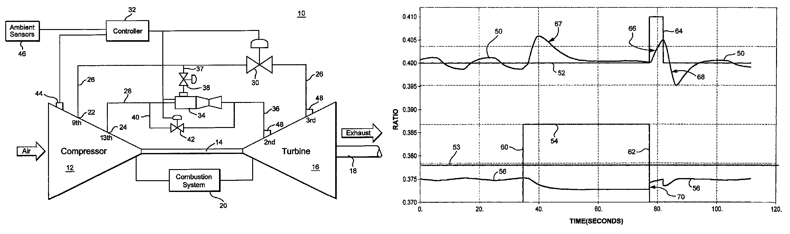
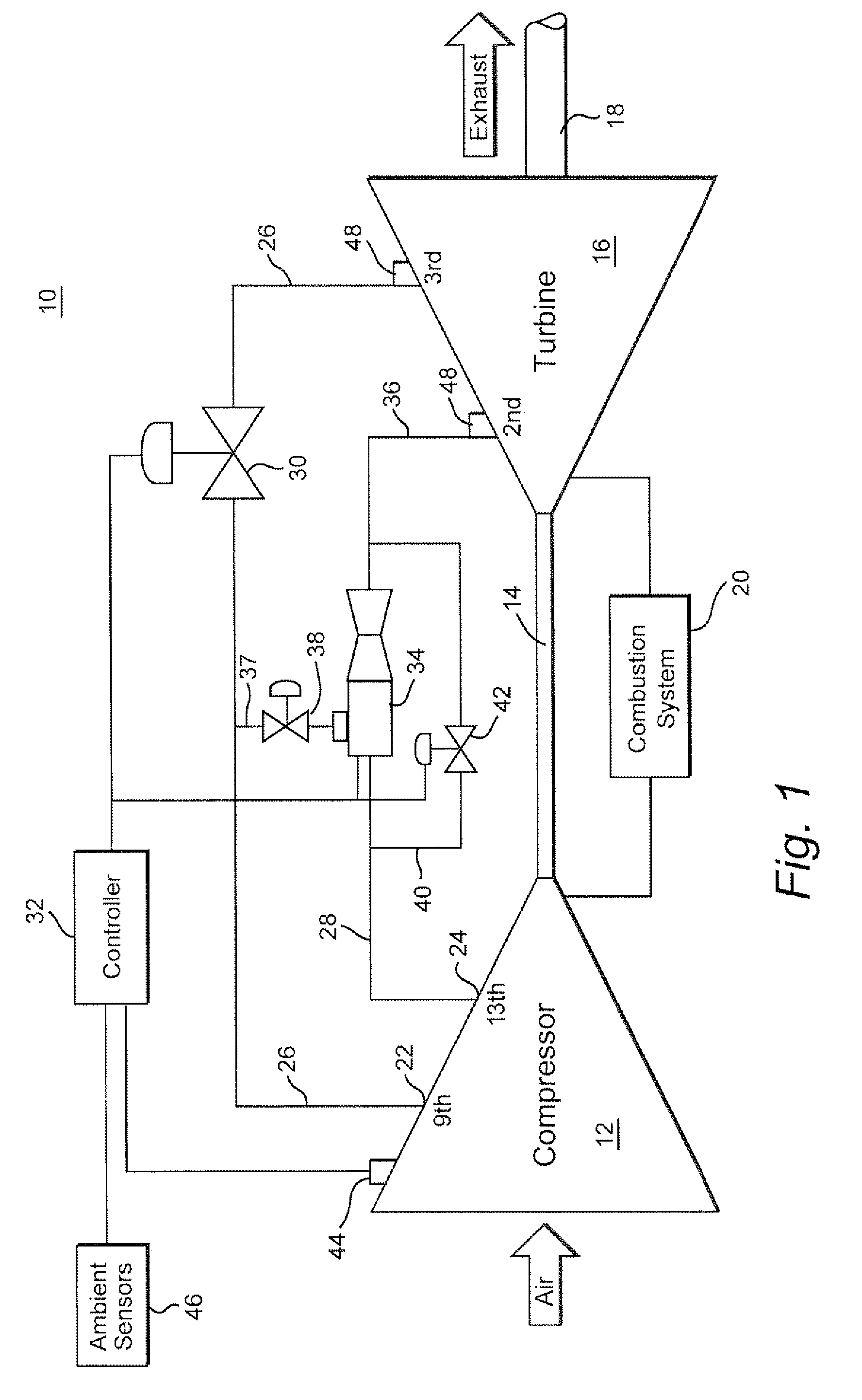
[0015]FIG. 1 is a schematic diagram of a gas turbine 10, such as an industrial gas turbine, having a multi-stage axial compressor 12 driven, through a drive shaft(s) 14 by a multi-stage axial turbine 16. Power generated by the turbine may be delivered by a power shaft 18 to a power generator (not shown). Air enters an inlet to the axial stage compressor and is progressively pressurized by successive stages of the compressor. High pressure air from the last stage of the compressor is ducted to a combustion system 20 where the air is mixed with fuel and combusts. High pressure combustion gases pass through the stages of the turbine, which generally comprise alternating rows of buckets and vanes. The hot combustion gases drive the turbine by rotating the annular arrays of buckets in the turbine. The gas pressure in the turbine progressively reduces as the gases pass through the stages of the turbine.

[0016]Cooling air cools the buckets and vanes of the turbine. The cooling air is typica...


PUM


Abstract

A method for controlling the generation of turbine cooling air from air extracted from a compressor of a gas turbine including: extracting compressed air from a low pressure and a high pressure stage of the compressor; adding in an ejector the compressed air from the low pressure stage to the air from the high pressure stage and discharging the combined air as turbine cooling air; bypassing the ejector with a bypass portion of the extracted compressed air from the high pressure stage; in response to turning on the flow of extracted compressed air from the low pressure stage, changing a set point for an actual pressure ratio that includes a pressure of the turbine cooling air, and adjusting the bypass flow in response to the changed set point to cause the actual pressure ratio to approach the changed set point.

Description

BACKGROUND OF THE INVENTION[0001]The invention relates generally to extracting compressor air to provide cooling air for a turbine in a gas turbine and, more particularly to establishing control set points for the extraction of compressor air.[0002]In industrial gas turbine engines, air is extracted from one or more stages of the compressor and applied to cool the turbine. The extraction of compressor air is commonly referred to as bleeding air from the compressor. The extracted compressor air is applied as cooling air that passes through internal cooling passages to the turbine blades and buckets.[0003]The air extracted from the compressor for turbine cooling reduces the amount of air flowing through the compressor and to the combustion section of the gas turbine. This reduction in compressed air to the combustor may, at times, have under desirable effects on the performance of the combustor and the total performance of the gas turbine. Control systems are employed to regulate the ...

Claims


Application Information

Patent Timeline
Patent Type & Authority Patents(United States)
IPC IPC(8): F02C7/18F02C9/18
CPCF02C6/08F02C7/18F02C9/18
Inventor CHILDERS, PRISCILLADISCH, MARKNEWTON, III, CURTISBALL, JR., DAVID WESLEYWHALING, KENNETH NEILTRUESDALE, ALAN MEIER
Owner GE INFRASTRUCTURE TECH INT LLC
Why Eureka
Try Eureka