Cryogenic freezing apparatus

a technology of freezing apparatus and pipe, which is applied in the field of improved pipe freezing apparatus, can solve the problems of affecting the use of the cooling apparatus, difficult to transport equipment, and high cost, and achieves the effect of convenient repair or replacement of the pipe section and easy adaptability to us

Active Publication Date: 2012-08-14
CRYOSTOP LLC
View PDF35 Cites 9 Cited by
  • Summary
  • Abstract
  • Description
  • Claims
  • Application Information

AI Technical Summary

Benefits of technology

[0011]The present invention is directed to an improved pipe freezing apparatus for use in freezing a plug of liquid within a pipe to facilitate repair or replacement of a pipe section downstream of the plug without the need to drain liquid from the pipe before repairs. The invention relates especially to a pipe freezing apparatus that is readily adaptable for use with pipes of different diameters, eliminating the need for a different pipe freezing apparatus for each diameter pipe.
[0014]A pipe freezing apparatus kit will include a plurality of sets of four adapter plates, each set forming two adapter plates, with the plates of each set having openings of a diameter different from the diameter of the openings in the plates of another set. By selecting the adapter plates having diameters corresponding to the diameter of the pipe to be frozen, the common chamber can be used, thereby significantly reducing the weight and cost.
[0018]In use, adapter plates, each having an inner cutout with a radius of curvature corresponding to the radius of curvature of the pipe to be repaired are attached, e.g., bolted, to the end wall sections of the chamber sections. The chamber sections are positioned on opposite sides of the pipe above the area that is to be repaired with a compressible gasket being positioned between the cylinder sections. Compressible tape is also wrapped around the pipe at the ends of the chamber to prevent leakage between the adapter plates and the pipe. The gaskets and tape are made of a compressible material, such as a neoprene and ethylene propylene rubber blend, that does not become brittle at the freezing temperatures.
[0019]The cylinder sections are then clamped together to compress the gaskets, preventing leakage between the chamber sections, or the interfaces of the adapter plates with the pipe. Clamping may be effected with a band clamp comprised of two band sections, one section being attached to each cylinder section, and T-bolts to adjustably draw the band ends toward each other.

Problems solved by technology

This time consuming and expensive procedure has been largely replaced through the use of pipe freezing devices that freeze a plug of liquid inside the pipe upstream of the pipe section that is to be repaired or replaced.
As the refrigerant evaporates, heat is extracted from the pipe and fluid within the section of pipe enclosed by the chamber, resulting in freezing of the liquid within the section of pipe enclosed by the chamber.
As a result, the equipment is difficult to transport and costly.
However, these inserts are cumbersome, often falling out when placing the chamber sections around a pipe.

Method used


Image

  • Cryogenic freezing apparatus
  • Cryogenic freezing apparatus
  • Cryogenic freezing apparatus

Examples


Embodiment Construction

[0031]In the following description, terms such as horizontal, upright, vertical, above, below, beneath, and the like, are used solely for the purpose of clarity in illustrating the invention, and should not be taken as words of limitation. The drawings are for the purpose of illustrating the invention and are not intended to be to scale.

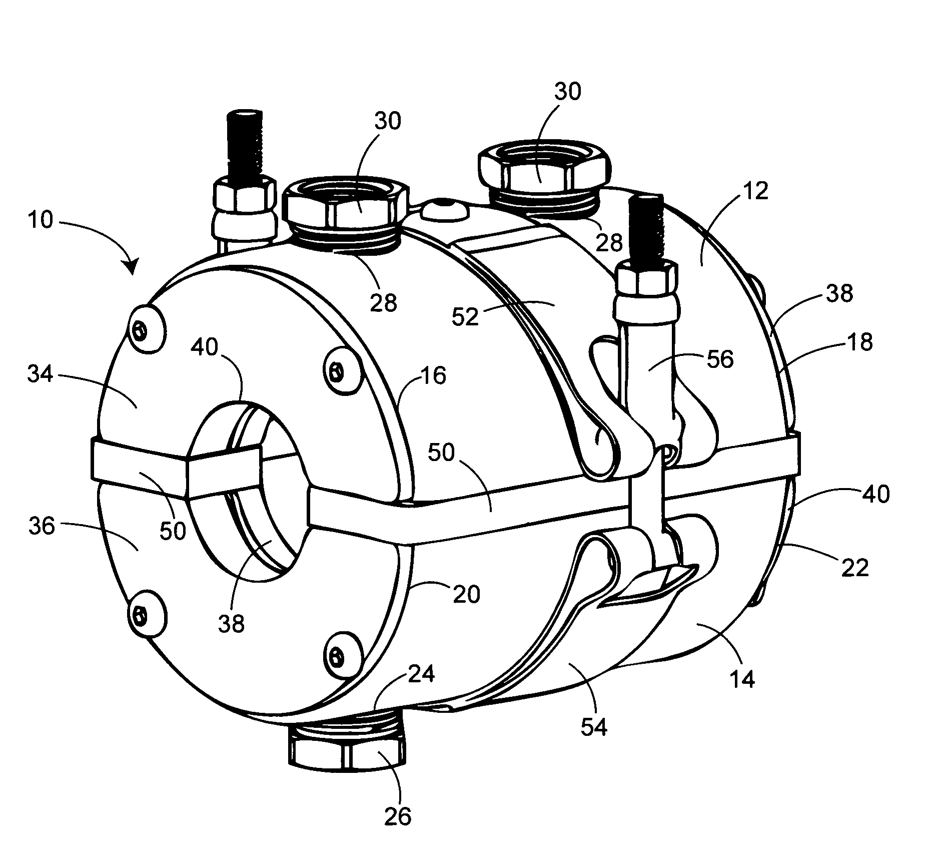
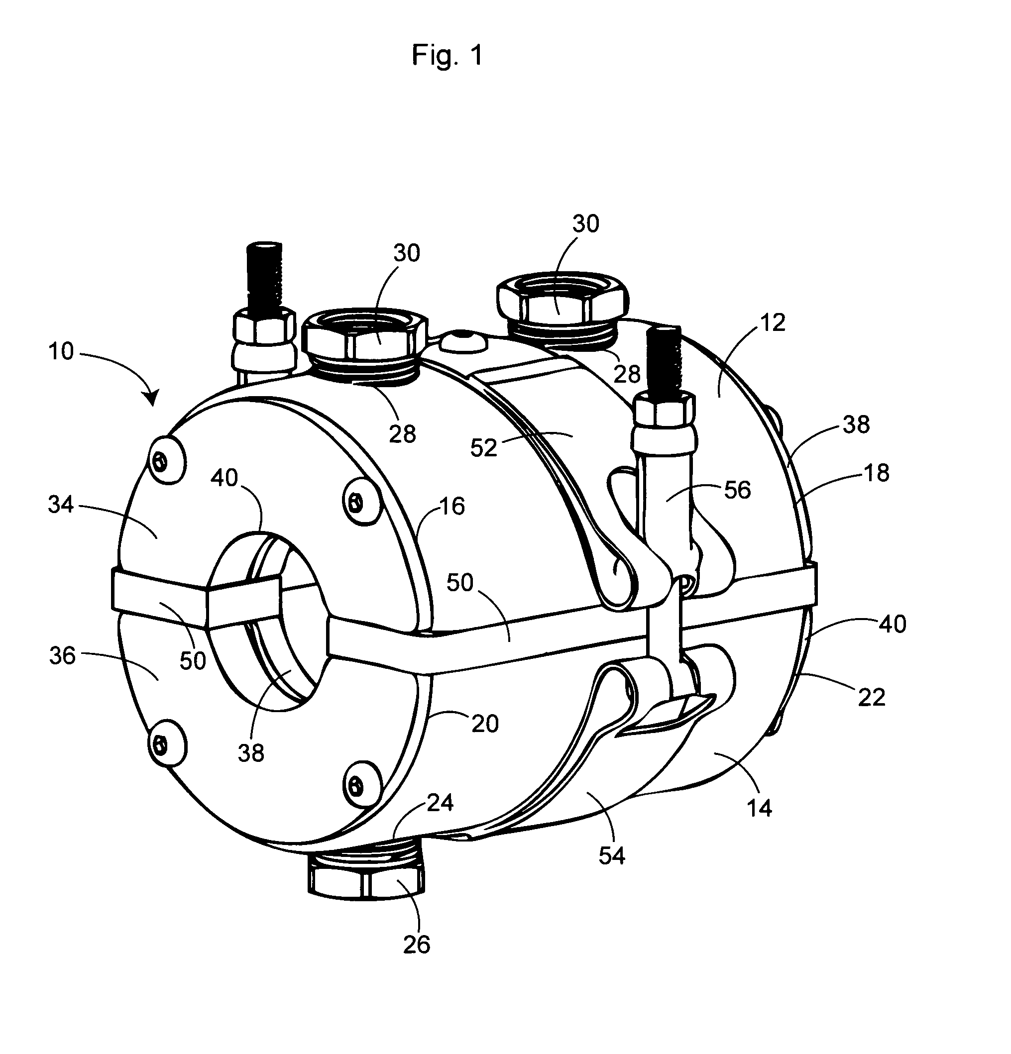
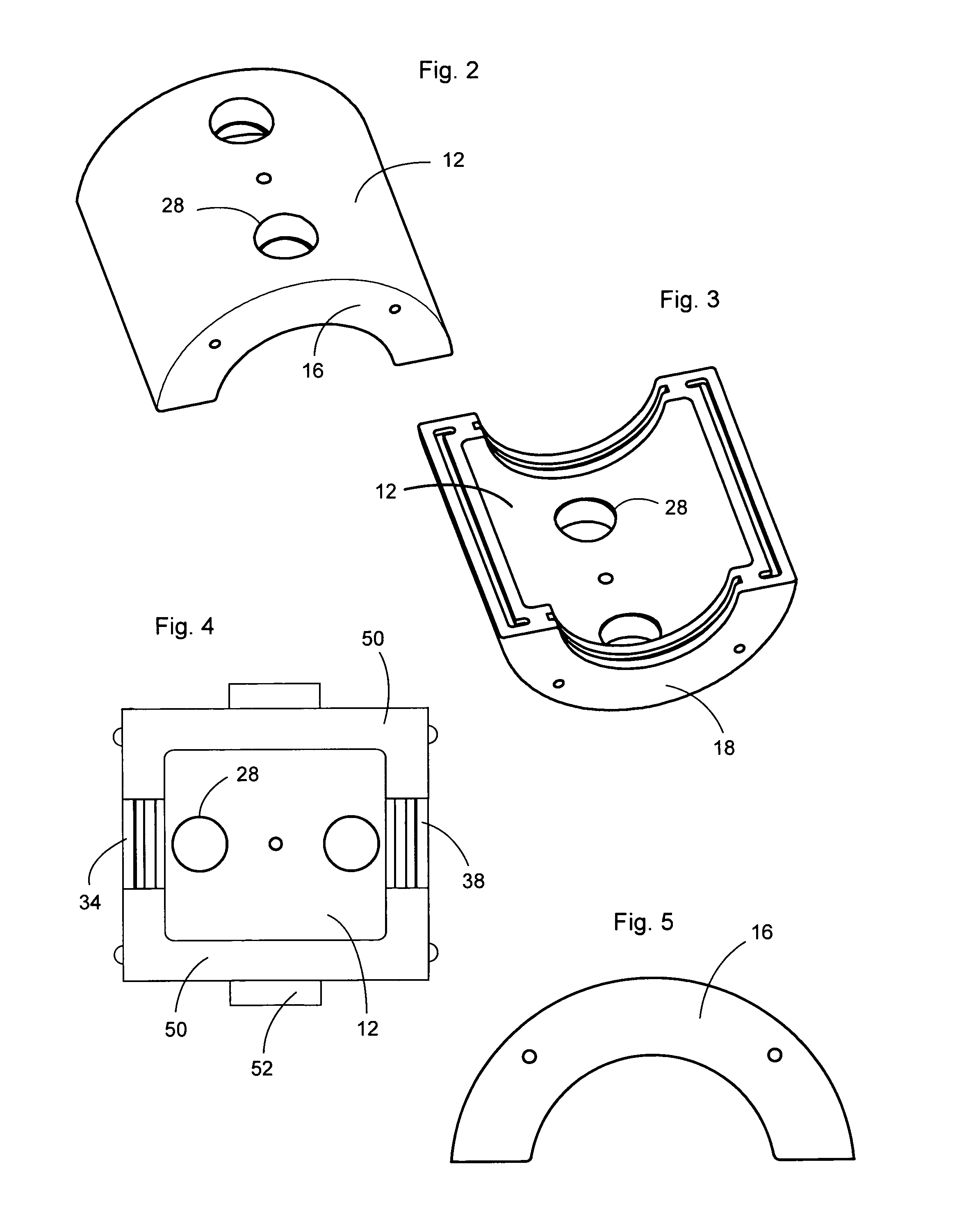
[0032]The freezing device of the present invention, generally 10, is comprised of a first chamber section 12 mating with a second chamber section 14, which together form a chamber with a hollow interior and end walls with outer faces and circular pipe receiving openings. Chamber section 12 includes opposed, parallel end walls 16 and 18 transverse to the axis of the chamber. Similarly, chamber section 14 includes opposed, parallel end walls 20 and 22 transverse to the axis of the chamber. Each wall includes spaced, threaded bolt holes. Chamber 12 includes an inlet 24 with a threaded bushing 26 for attachment of a supply hose, not shown, from a refrige...


PUM


Abstract

A kit is described for use in freezing liquid within a first pipe of a given first diameter and a second pipe of a given second diameter less than the given first diameter. The kit includes a multi-section refrigerant chamber adapted for attachment around a pipe, the chamber having end mounting walls with openings having a diameter greater than the first given diameter; a pair of first adapter plates attachable to the outer faces of the end walls of the chamber sections, the first adapter plates having central pipe receiving openings with a diameter equal to the first given diameter; and a pair of second adapter plates attachable to the outer faces of the end walls of the chamber sections, the second adapter plates having central pipe receiving opening with a diameter equal to the second given diameter. A compressible gasket can be inserted between the chamber sections.

Description

BACKGROUND OF THE INVENTION[0001](1) Field of the Invention[0002]The present invention is directed to an improved pipe freezing apparatus for use in freezing a plug of liquid within a pipe to facilitate repair or replacement of a pipe section, and in particular to a pipe freezing apparatus that is readily adaptable for use with pipes of different diameters.[0003](2) Description of the Prior Art[0004]Repairing or replacing sections of fluid carrying pipe historically required draining of the pipe, and then cutting and replacing the pipe section. This time consuming and expensive procedure has been largely replaced through the use of pipe freezing devices that freeze a plug of liquid inside the pipe upstream of the pipe section that is to be repaired or replaced. The frozen plug prevents liquid from flowing from the pipe during repair. After the repairs have been made, the plug is allowed to thaw so that liquid can again flow through the pipe.[0005]Pipe freezing devices are comprised ...

Claims


Application Information

Patent Timeline
Patent Type & Authority Patents(United States)
IPC IPC(8): F25D23/12
CPCF16L55/103
Inventor INGRAM, MICHAEL T.
Owner CRYOSTOP LLC
Why Eureka
Try Eureka